


Description
The DRV8825 is a complete Microstepping Motor Driver with a built-in translator for easy operation. The breakout board features adjustable current limiting, over-current and over-temperature protection, and six different microstep resolutions. It operates from 8.2 V to 45 V and can deliver up to approximately 1.5 A Current per phase without a heat sink or forced airflow. It is rated for 2.2 A Current per coil with sufficient additional cooling.
Features
- Max. Operating Voltage: 45V
- Min. Operating Voltage: 8.2V
- Max. Current Per Phase: 2.5A
- Microstep resolution: Full step, 1/2 step, 1/4 step, 1/8 step, 1/16 step 1/32 step
- Over temperature shutdown circuit
- Under-voltage lock out
- Over current shutdown
- Dimensions: 20.5 x 15.5 mm (0.8″ × 0.6″)
- Short-to-ground and shorted-load protection
- Low RDS(ON) outputs
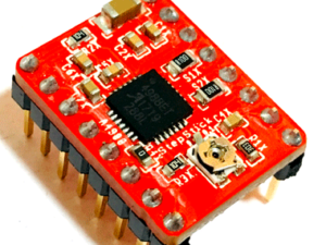
Understanding DRV8825 Driver Module
The DRV8825 driver has total of 16 pins which are as follows:
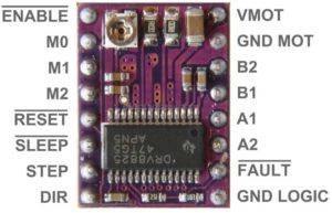
VMOT and GND MOT supply power to the motor. Any voltage between 8.2V and 45V can be connected to this pin. The module doesn’t have a logic supply pin because the DRV8825 draws its power from the motor power supply using an internal 3V3 voltage regulator. You should, however, connect your microcontroller’s ground to the GND LOGIC pin.
Microstep Selection Pins: The DRV8825 driver has three-step resolution selector inputs, i.e., M0, M1 & M2. By setting appropriate logic levels to those pins we will set the motors to at least one of the six-step resolutions.
| M0 | M1 | M2 | Microstep Resolution |
| Low | Low | Low | Full step |
| High | Low | Low | Half step |
| Low | High | Low | 1/4 step |
| High | High | Low | 1/8 step |
| Low | Low | High | 1/16 step |
| High | Low | High | 1/32 step |
| Low | High | High | 1/32 step |
| High | High | High | 1/32 step |
These three microstep selection pins are pulled LOW by on-board pull-down resistors, so if you leave them unconnected, the motor will operate in full step mode.
The DRV8825 has two control inputs: STEP and DIR. STEP input controls the micro-steps of the motor. The faster the pulses, the faster the motor will rotate. The DIR input controls the spinning direction of the motor. Pulling it HIGH drives the motor clockwise and pulling it LOW drives the motor anti-clockwise
The DRV8825 has three separate inputs for controlling its power states: EN, RST, and SLP. The EN pin is always active low input by default which enables the driver. SLP Pin is active low input. Pulling this pin LOW puts the driver in sleep mode, minimizing the facility consumption. The RST is a lively low input which when pulled LOW, all STEP inputs are ignored. It also resets the driver by setting the internal translator to a motor initial stage.
There are 4 output pins as B2, B1, A2, A1. We can connect any bipolar stepper motor, such as NEMA 17, having voltages between 8.2V to 45 V to those pins. Each output pin on the module can deliver up to 2.2A to the motor
The DRV8825 has a FAULT output that drives LOW whenever the H-bridge FETs are disabled as the result of over-current protection or thermal shutdown. The Fault pin is typically shorted to the SLEEP pin; therefore, whenever the Fault pin is driven LOW, the entire chip is disabled. And it will remain disabled until it is either RESET or Motor Voltage VMOT is removed and reapplied.
NB: It is safe to use the DRV8825 Driver without a heat sink if the current rating is up to 1.5A. For achieving more than 1.5A per coil, i.e. 2.2A, a heat sink or other cooling method is required.
Current limiting
Before running the motor, you must limit the maximum current flowing through the stepper coils so that it does not exceed the motor’s rated current. The DRV8825 driver includes a small trimmer potentiometer for setting the current limit.
There are two methods for making this adjustment:
Method 1:
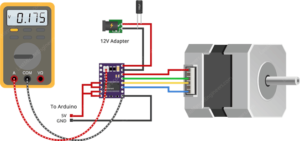
In this method, the current limit is determined by measuring the voltage (Vref) at the “ref” pin.
- Take a look at the datasheet for your stepper motor. Make a note of the rated current. In our case, NEMA 17 200steps/rev, 12V 350mA is used.
- Disconnect the three microstep selection pins to put the driver in full-step mode.
- Hold the motor in a fixed position without clocking the STEP input.
- Measure the voltage (Vref) on the metal trimmer pot as you adjust it.
- Adjust the Vref voltage by using the formula
Vref = Current Limit / 2
For example, if your motor is rated at 350mA, you would set the reference voltage to 0.175V.
Method 2:
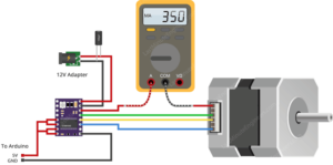
In this method, the current limit is determined by measuring the current flowing through the coil.
- Take a look at the datasheet for your stepper motor. Make a note of the rated current. In our case, NEMA 17 200steps/rev, 12V 350mA is used.
- Disconnect the three microstep selection pins to put the driver in full-step mode.
- Hold the motor in a fixed position without clocking the STEP input.
- Put the ammeter in series with one of the coils on your stepper motor and measure the actual current flowing.
- Take a small screwdriver and adjust the current limit potentiometer until you reach the rated current.
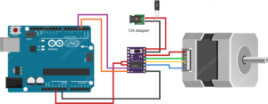
Wiring a DRV8825 Stepper Motor Driver to an Arduino
The connections are straightforward. Start by connecting the RST pin to the adjacent SLP/SLEEP pin and 5V on the Arduino to keep the driver enabled. Connect the GND LOGIC pin to the Arduino’s ground pin. Connect the DIR and STEP input pins to the Arduino’s digital output pins #2 and #3. Connect the stepper motor to the B2, B1, A1, and A2 pins. Actually, the DRV8825 module is conveniently laid out to match the 4-pin connector on bipolar stepper motors, so that shouldn’t be a problem.
Keep the microstep selection pins disconnected if you want to run the motor in full step mode. Finally, connect the motor power supply to the VMOT and GND MOT pins. Remember to put a large 100μF decoupling electrolytic capacitor across the motor power supply pins to avoid large voltage spikes.
Arduino Code – Without a Library
The sketch below will show you how to control the speed and spinning direction of a bipolar stepper motor using the DRV8825 stepper motor driver and can serve as the basis for more practical experiments and projects.
// Define pin connections & motor's steps per revolution
const int dirPin = 2;
const int stepPin = 3;
const int stepsPerRevolution = 200;

void setup()
{
	// Declare pins as Outputs
	pinMode(stepPin, OUTPUT);
	pinMode(dirPin, OUTPUT);
}
void loop()
{
	// Set motor direction clockwise
	digitalWrite(dirPin, HIGH);

	// Spin motor slowly
	for(int x = 0; x < stepsPerRevolution; x++)
	{
		digitalWrite(stepPin, HIGH);
		delayMicroseconds(2000);
		digitalWrite(stepPin, LOW);
		delayMicroseconds(2000);
	}
	delay(1000); // Wait a second

	// Set motor direction counterclockwise
	digitalWrite(dirPin, LOW);

	// Spin motor quickly
	for(int x = 0; x < stepsPerRevolution; x++)
	{
		digitalWrite(stepPin, HIGH);
		delayMicroseconds(1000);
		digitalWrite(stepPin, LOW);
		delayMicroseconds(1000);
	}
	delay(1000); // Wait a second
}
Code Explanation:
The sketch begins by defining the Arduino pins to which the DRV8825’s STEP and DIR pins are connected. A variable called stepsPerRevolution is also defined. You can set it to match the specs of your stepper motor.
In the setup section, all motor control pins are configured as digital OUTPUT.
In the loop section, the motor is rotated slowly clockwise and then rapidly counterclockwise with one second intervals.
Controlling the Spinning Direction: To control the spinning direction of the motor, the DIR pin is set HIGH or LOW. A HIGH input turns the motor clockwise, while a LOW input turns it counterclockwise.
Controlling Speed: The frequency of pulses sent to the STEP pin determines the speed of the motor. The higher the pulse frequency, the faster the motor runs. A pulse is nothing but pulling the output HIGH, waiting a bit, then pulling it LOW and waiting again. By adjusting the delay between two pulses, you can alter the frequency of the pulses and thus the speed of the motor.
Arduino Code – Using AccelStepper library
Controlling a stepper without a library is perfectly fine for simple, single motor applications. However, if you want to control multiple steppers, you’ll need to use a library.
So, for our next experiment, we will use an advanced stepper motor library called AccelStepper library. It supports:
- Acceleration and deceleration.
- Multiple simultaneous steppers, with independent concurrent stepping on each stepper.
This library is not included in the Arduino IDE, so you must first install it.
Library Installation
To install the library navigate to Sketch > Include Libraries > Manage Libraries… Wait for Library Manager to download the library index and update the list of installed libraries.
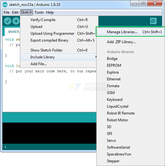
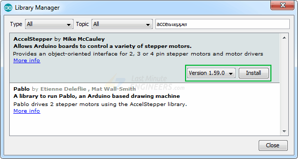
Filter your search by typing ‘accelstepper’. Click on the first entry and then select Install.
Arduino Code
Here is a simple sketch that accelerates the stepper motor in one direction and then decelerates to come to rest. After one revolution, the motor reverses its spinning direction and repeats the process.
// Include the AccelStepper Library
#include <AccelStepper.h>

// Define pin connections
const int dirPin = 2;
const int stepPin = 3;

// Define motor interface type
#define motorInterfaceType 1

// Creates an instance
AccelStepper myStepper(motorInterfaceType, stepPin, dirPin);

void setup() {
	// set the maximum speed, acceleration factor,
	// initial speed and the target position
	myStepper.setMaxSpeed(1000);
	myStepper.setAcceleration(50);
	myStepper.setSpeed(200);
	myStepper.moveTo(200);
}

void loop() {
	// Change direction once the motor reaches target position
	if (myStepper.distanceToGo() == 0)
		myStepper.moveTo(-myStepper.currentPosition());

	// Move the motor one step
	myStepper.run();
}
Code Explanation:
The sketch begins by including the newly installed AccelStepper library.
#include <AccelStepper.h>First, the Arduino pins are defined, to which the DRV8825’s STEP and DIR pins are connected. The motorInterfaceType is also set to 1. (1 means an external stepper driver with step and direction pins).
// Define pin connections
const int dirPin = 2;
const int stepPin = 3;

// Define motor interface type
#define motorInterfaceType 1
Following that, an instance of the stepper library named myStepper is created.
AccelStepper myStepper(motorInterfaceType, stepPin, dirPin);In the setup function, the maximum permitted speed of the motor is set to 1000 (the motor will accelerate up to this speed when we run it). The acceleration/deceleration rate is then set to add acceleration and deceleration to the stepper motor’s movements.
The desired constant speed is set to 200. And, because the NEMA 17 takes 200 steps per turn, the target position is also set to 200.
void setup() {
	myStepper.setMaxSpeed(1000);
	myStepper.setAcceleration(50);
	myStepper.setSpeed(200);
	myStepper.moveTo(200);
}
In the loop function, an if statement is used to determine how far the motor needs to travel (by reading the distanceToGo property) before reaching the target position (set by moveTo). When the distanceToGo reaches zero, the motor is rotated in the opposite direction by setting the moveTo position to negative of its current position.
At the bottom of the loop, you’ll notice that the run() function is called. This is the most critical function because the stepper will not move unless this function is executed.
void loop() {
	if (myStepper.distanceToGo() == 0)
		myStepper.moveTo(-myStepper.currentPosition());

	myStepper.run();
}
Package includes: 1×DRV8825 Stepper Motor Driver Module
Reviews
There are no reviews yet.