Description
The A4988 driver Stepper Motor Driver is a complete micro-stepping motor driver with built-in converter, easy to operate. It operates from 8 V to 35 V and can deliver up to approximately 1 A per phase without a heat sink or forced air flow (it is rated for 2 A per coil with sufficient additional cooling).
SPECIFICATIONS
- Supply Voltage : 8-35 VDC.
- Current : 1.0A (no heatsink ).
- Current : 2.0A (with heat-sinking).
- logic input : 3 – 5.5V .
- Automatic current decay mode detection / choice.
- Mixed with slow current decay mode.
If you are planning on building your own 3D printer or a CNC machine, you will need to control a bunch of stepper motors. And having one Arduino control all of them can take up a lot of the processing and not leave you a lot of room to do anything else; unless you use a self-contained dedicated stepper motor driver – A4988.
It can control both speed and spinning direction of a bipolar stepper motor like NEMA 17 with just two pins.
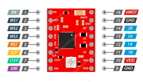
A4988 Motor Driver Pinout
The A4988 driver has total 16 pins that interface it to the outside world. The connections are as follows:
Cooling System – Heatsink
Excessive power dissipation of the A4988 driver IC results in the rise of temperature that can go beyond the capacity of IC, probably damaging itself. Even if the A4988 driver IC has a maximum current rating of 2A per coil, the chip can only supply approximately 1A per coil without getting overheated. For achieving more than 1A per coil, a heat sink or other cooling method is required.
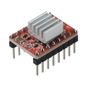
The A4988 driver usually comes with a heatsink. It is advisable to install it before you use the driver.
Current limiting
Before using the motor, there’s a small adjustment that we need to make. We need to limit the maximum amount of current flowing through the stepper coils and prevent it from exceeding the motor’s rated current.
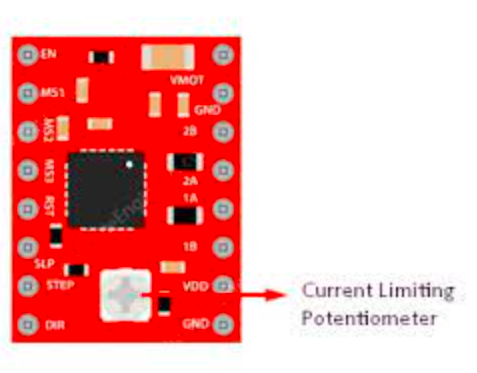
There’s a small trimmer potentiometer on the A4988 driver that can be used to set the current limit. You should set the current limit to be at or lower than the current rating of the motor. To make this adjustment there are two methods:
Method 1:
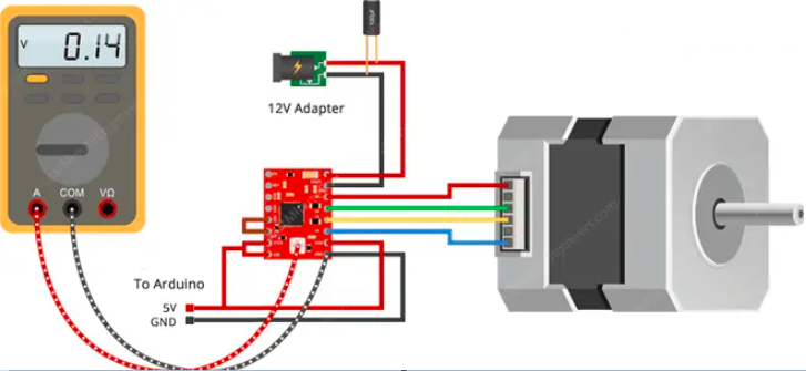
In this method we are going to set the current limit by measuring the voltage (Vref) on the “ref” pin.
- Take a look at the datasheet for your stepper motor. Note down it’s rated current. In our case we are using NEMA 17 200steps/rev, 12V 350mA.
- Put the driver into full-step mode by leaving the three microstep selection pins disconnected.
- Hold the motor at a fixed position by not clocking the STEP input.
- Measure the voltage (Vref) on the metal trimmer pot itself while you adjust it.
- Adjust the Vref voltage using the formula
Current Limit = Vref x 2.5
For example, if your motor is rated for 350mA, you would adjust the reference voltage to 0.14V.
Tip: An easy way to make adjustments is to use an alligator clip on the shaft of a metal screwdriver and attach that to your multimeter so that you can measure and adjust the voltage with the screwdriver at the same time.
Method 2:
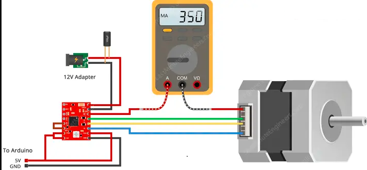
In this method we are going to set the current limit by measuring the current running through the coil.
- Take a look at the datasheet for your stepper motor. Note down it’s rated current. In our case we are using NEMA 17 200steps/rev, 12V 350mA.
- Put the driver into full-step mode by leaving the three microstep selection pins disconnected.
- Hold the motor at a fixed position by not clocking the STEP input. Do not leave the STEP input floating, connect it to logic power supply(5V)
- Place the ammeter in series with one of the coils on your stepper motor and measure the actual current flowing.
- Take a small screwdriver and adjust the current limit potentiometer until you reach rated current.
You will need to perform this adjustment again if you ever change the logic voltage(VDD)
Getting started with the A4988 Driver Module Stepper Motor Driver with Heatsink
Now that you have wired up the driver and set the current limit, it is time to connect the Arduino to the computer and upload some code. You can upload the following example code to your Arduino using the Arduino IDE. For this specific example, you do not need to install any libraries. This sketch controls both the speed, the number of revolutions, and the spinning direction of the stepper motor.
Hardware required
- 4-lead Nema 17 Stepper Motor 17HS4401
- A4988 Driver Module Stepper Motor Driver
- Jumpe wires
- 12v DC Adaptor
- Electrolytic capacitor 100µF
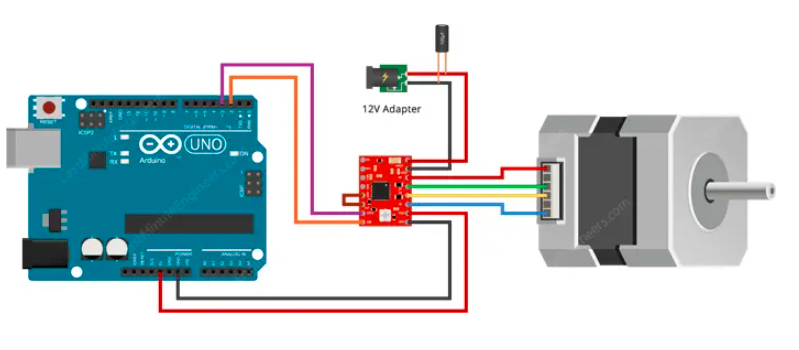
Connecting the Hardware
Connections are fairly simple. Start by connecting VDD and GND(next to VDD) to the 5V and ground pins on the Arduino. DIR and STEP input pins are connected to #2 & #3 digital output pins on Arduino respectively. connect the stepper motor to the 2B, 2A, 1A & 1B pins. Actually A4988 is conveniently laid out to match the 4-pin connector on several bipolar motors so, that shouldn’t be a problem.
Warning: Connecting or disconnecting a stepper motor while the driver is powered can destroy the driver.
Next, Connect RST pin to the adjacent SLP/SLEEP pin to keep the driver enabled. Also keep the microstep selection pins disconnected to operate the motor in full step mode. Finally, connect the motor power supply to the VMOT and GND pins. Remember to put a large 100µF decoupling electrolytic capacitor across motor power supply pins, close to the board.
Setting up the library
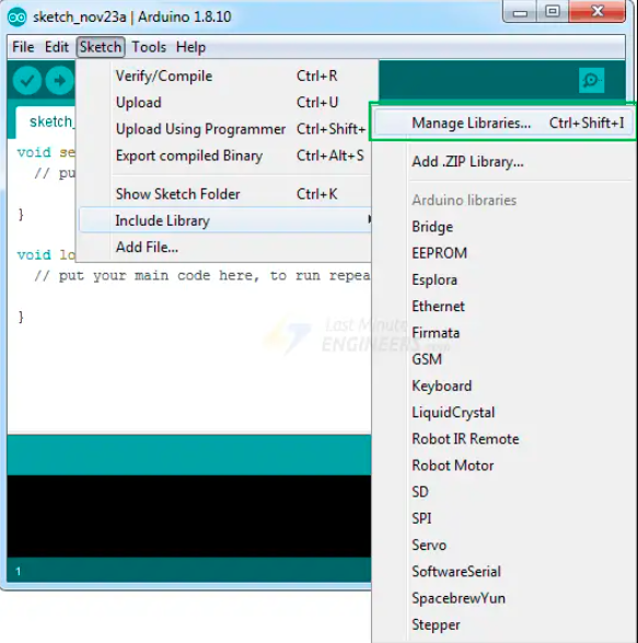
To install the library navigate to the Sketch > Include Library > Manage Libraries… Wait for Library Manager to download libraries index and update list of installed libraries.
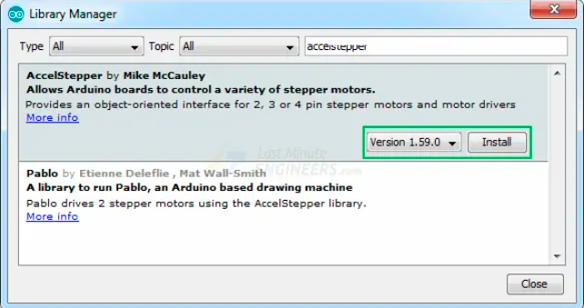
Filter your search by typing ‘accelstepper’. Click on the first entry, and then select Install.
Upload the sample sketch
This sketch controls both the speed, the number of revolutions, and the spinning direction of the stepper motor.