Description
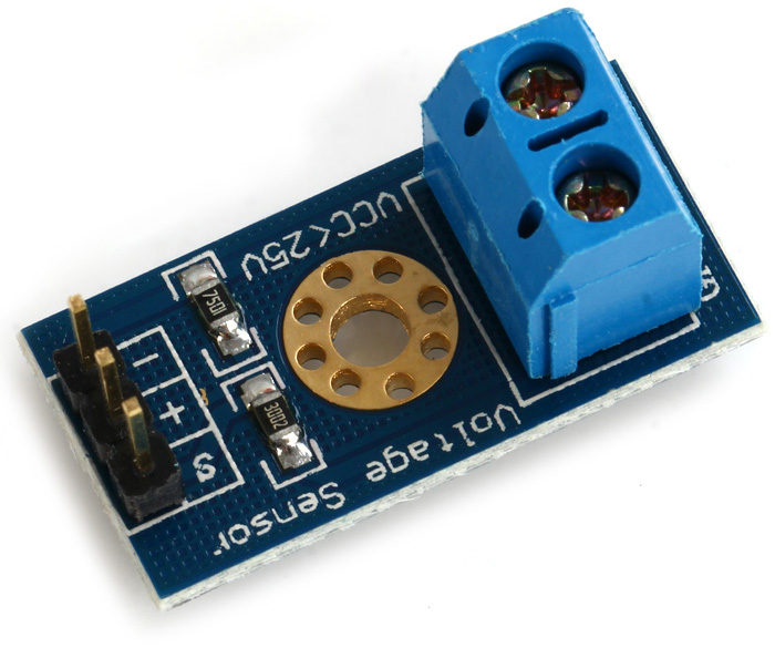
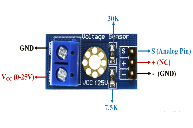
A simple but very useful module which uses a potential divider to reduce any input voltage by a factor of 5. This allows you to use the analogue input of a microcontroller to monitor voltages much higher than it capable of sensing.
Arduino analog input voltage work up to 5V, then the input voltage of the voltage detection module can not be greater than 5V × 5 = 25V (3.3V if used system, the input voltage can not exceed 3.3Vx5 = 16.5V).
Because Arduino AVR chips used in 10 AD, so the resolution of this module is the analog 0.00489V (5V / 1023), so the voltage detection module detects a minimum input voltage of 0.00489V × 5 = 0.02445V.
Specification
- Divider ratio: 5:1
- Resistor Tolerance: 1%
- Max input voltage: 25V
- Resistor Value: 30K/7.5K Ohm
- Input voltage range: 0V-25V
- Voltage detection range: DC0.02445V-25V
- Voltage analog resolution: 0.00489V
Getting started with the Voltage Sensor module 5V
In this project, we will learn how to measure voltages using Arduino by interfacing a Voltage Sensor with Arduino. Using this Arduino Voltage Sensor interface, you can measure voltages up to 25V.
Step1: Hardware required
Step2: Connecting the Hardware
Find yourself a 9 volt battery and connect it, your voltage sensor module and Arduino as shown below.

Step3: CODE
Enter the following sketch, upload it
const int voltageSensor = A0;
float vOUT = 0.0;
float vIN = 0.0;
float R1 = 30000.0;
float R2 = 7500.0;
int value = 0;
void setup()
{
Serial.begin(9600);
Serial.print(” Measure > 25V “);
delay(2000);
}
void loop()
{
value = analogRead(voltageSensor);
vOUT = (value * 5.0) / 1024.0;
vIN = vOUT / (R2/(R1+R2));
Serial.print(“Input = “);
Serial.println(vIN);
delay(500);
}
Step4: Upload the sample sketch
If you open your Arduino serial monitor you will be able to see the voltage.


