

Description
The TB6600 stepper motor driver IC is a very easy, effective, and professional device that can drive 2-phase stepper motors. Compatible with any type of microcontroller and Arduino to generate 5V digital output pulse signals. The TB6600 stepper motor driver has a wide input power range, (9-42VDC) of power supply, and generates 4 Amps peak current, supporting direction control and speed that is sufficient for most stepper motors.
Features
- It is a Bipolar H-bridge DC driver.
- 8 output current types are optional up to 4 Amps. (0.5A to 3.5A)
- Divides up to 32 selectable 6 subdivision modes.
- Provides 8 kinds of micro steps (1, 2/A, 2/B, 4, 8, 16, 32).
- Provides high-speed photoelectric separation of the input signal.
- Full standard single pulse interface. > Offline hold function.
- Used in more harsh environments due to a semi-enclosed body.
- Provides a semi-automatic power lock function with energy saving.
Applications
The TB6600 stepper motor driver module applications are:
- Antennas.
- Setting the position of stepper motors.
- CNC (computer numerical control) machines
- 3D printers.
- High-level applications.
- Controlling speed, position, and direction of rotation of stepper motors.
- DSLR and Video Cameras.
- ATMs.
- Engraving machines.
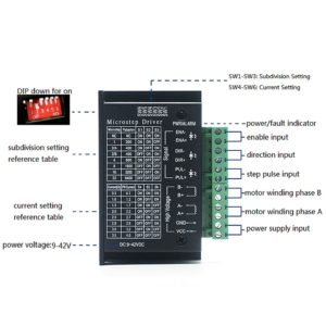
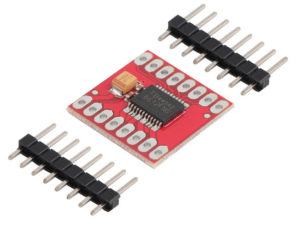
TB6600 Pin Configuration
- Pin 1: ENA- (ENA): This pin refers to the negative enable pin of the module.
- Pin 2: ENA+(+5V): This pin refers to the positive enable pin, which is the +5V pin of the module.
- Pin 3: DIR-(DIR): This pin refers to the negative direction of the motor.
- Pin 4: DIR+(+5V): This pin refers to the positive direction of +5V.
- Pin 5: PUL-(PUL): This pin refers to the negative pulse. (For controlling rotations steps of the motor)
- Pin 6: PUL+(+5V): This pin refers to the positive pulse of the motor.
- Pin 7: B-: This pin refers to the negative lead stepper motor coil wire 2.
- Pin 8: B+: This pin refers to the position lead of stepper motor coil wire 2.
- Pin 9: A-: This pin refers to the negative lead of stepper motor coil wire 1.
- Pin 10: A+: This pin refers to the positive lead stepper motor coil wire 1.
- Pin 11: GND: This pin refers to the common ground connection of the module.
- Pin 12: VCC: This pin refers to the input supply voltage for the stepper motor driver module, which is 9V-42V.
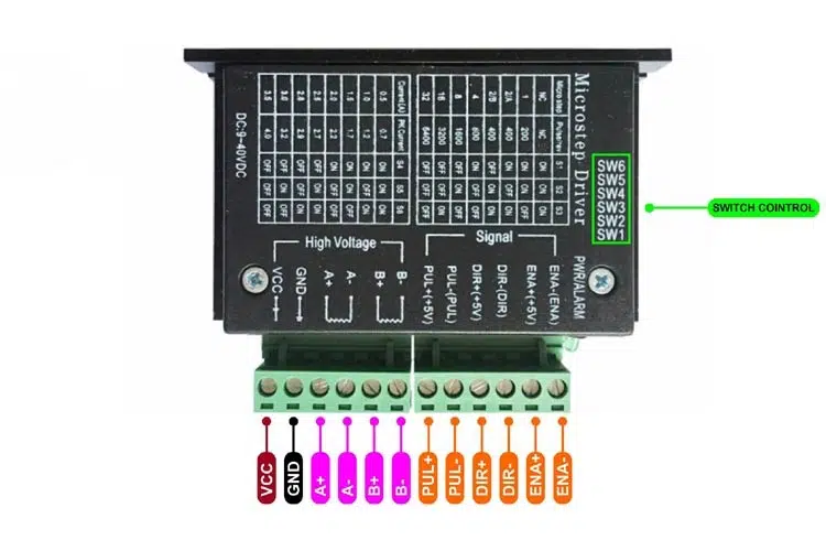
The in-built control/driver switches SW1, SW2, SW3, SW4, SW5, and SW6 are used to control the resolution of micro steps and used to limit the driver current. Switching of SW1, SW2, and SW3 changes the micro-step resolution from full step to 1/32 step.
How to use TB6600 with Arduino UNO?
The microcontroller or the Arduino can be used to control the speed, rotation direction, steps, or revolutions of the stepper motor. The TB6600 stepper motor driver module uses a bipolar H-bridge configuration and is operated in 3 modes such as wave mode, full-step mode, half-step mode, and micro-stepping mode. The microstrip resolution of the motor is set by using the control switches of the driver module. The TB6600 module is widely used in controlling the 2-phase stepper motors because it provides low voltage shutdown, overcurrent, and overheating protection.
This section explains how to use the TB6600 stepper motor driver module with the Arduino UNO. The components required are,
- Arduino UNO R3.
- TB6600 stepper motor driver 4A.
- Stepper motor.
- Jumper wires.
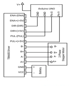
Make the connections as per the above diagram. Connections of TB6600 to Arduino, stepper motor, and supply are – DIR+(+5V) to Pin 8; PUL+(+5V) to pin 9; DIR-(DIR) and PUL-(PUL) to GND; A+, A-, B+, B- pins to the leads of the 2-phase stepper motor as shown in the diagram; VCC and GND to corresponding battery terminals. Upload the Arduino code and observe the rotation, speed, and steps of the 2-phase stepper motor.
Arduino Code:
#define dirPin 8
#define stepPin 9
void setup() {
// Declare pins as output:
pinMode(stepPin, OUTPUT);
pinMode(dirPin, OUTPUT);
// Set the spinning direction CW/CCW: (clockwise or counterclockwise)
digitalWrite(dirPin, HIGH);
}
void loop() {
// These four lines result in 1 step:
digitalWrite(stepPin, HIGH);
delayMicroseconds(500);
digitalWrite(stepPin, LOW);
delayMicroseconds(500);
}
When the DIR+(+5V) pin is set to high, the motor rotates in a clockwise (forward) direction and generates the square pulses with the step pin.
The microstrip resolution is changed by using the control switches SW1 and SW2. When SW1 is ON and SW2 is OFF, then micro step resolution becomes ¼ step. When SW1 is OFF and SW2 is ON, then it becomes ⅛ step. When SW1 and SW2 are OFF, then it becomes 1/32 step. When both switches are set, then it becomes a full step.
The following truth table shows the change in micro-step resolution.
| SW1 | SW2 | Microstep Resolution |
| OFF | OFF | 1/32 step |
| OFF | ON | ⅛ step |
| ON | OFF | ¼ step |
| ON | ON | Full Step |
To drive the stepper motor in an anticlockwise direction, then the TB6600 stepper motor driver 4.5A type module is used and the process is the same. Ensure that the current flowing in the motor should not exceed the peak current of the driver 4A. Use the control switches S4 and S6 to set the current flow.
Package includes:
1×TB6600 Stepper Motor Driver 4A DC9-42V
Reviews
There are no reviews yet.