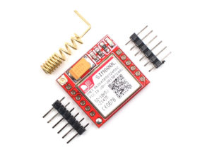
Description
This SIM900/A V3.8.2 module has a set of TTL level serial interface, a set of RS232 level serial interface, a set of power supply interface.
Basic features
- Quad-Band 850/ 900/ 1800/ 1900 MHz
- Dual-Band 900/ 1900 MHz
- GPRS multi-slot class 10/8GPRS mobile station class B
- Compliant to GSM phase 2/2+Class 4 (2 W @850/ 900 MHz)
- Class 1 (1 W @ 1800/1900MHz)
- Control via AT commands (GSM 07.07 ,07.05 and SIMCOM enhanced AT Commands)
- Low power consumption: 1.5mA(sleep mode)
- Operation temperature: -40°C to +85 °C
- Power supply range: voltage is 4.6-5.2v; current is 1A or more(the current is very important).
- Communication interface: The TTL level serial interface compatible 2.85 3.3 5v MCU
- Size:49*50mm
Getting started with the MINI V3.8.2 Wireless Data Transmission Extension Module GSM-GPRS SIM900A
In this Tutorials we are going to deal with GSM SIM900A (MINI V3.9.2) this is simple and easy to connect with Arduino. Other type should be has same principle on how to use it. Usually just use different power consumption. Like voltage and current. This type can connected to 5V directly, which has provided by Arduino.
Step1: Hardware required
In this tutorial, you will need :
1. GSM SIM900A (MINI V3.9.2)
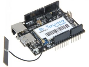
2. Arduino Uno Board
3. Jumper Wire
4. SIM card
Step2: Connecting the Hardware

Wire SIM900A module to Arduino UNO like this :
Arduino -> SIM900A
5V -> VCC
GND -> GND
10 -> 5VT
11 -> 5VR

1. Insert your SIM card to GSM module and lock it.
2. power up your gsm by connecting it to Arduino’s 5V and GND.
3. Connect the Antenna.
4. Now wait for some time (say 1 minute) and see the blinking rate of ‘status LED’ or ‘network LED’ //GSM module will take some time to establish connection with mobile network//
5. Once the connection is established successfully, the status/network LED will blink continuously every 3 seconds. You may try making a call to the mobile number of the sim card inside GSM module. If you hear a ring back, the gsm module has successfully established network connection.
6.You can see a TTL pin with 3VR, 3VT, 5Vr, 5VT, VCC and GND on your sim900a near your power supply pin. You have to connect GSM’s 5VT to Arduino D9 and GSM’s 5VR to Arduino’s D10 for serial communication between arduino and sim900a module.
Step3: Setting up the library
SoftwareSerial is a library of Arduino which enables serial data communication through other digital pins of Arduino. The library replicates hardware functions and handles the task of serial communication. To be able to interface gsm module with arduino, you will have to download this library and extract it into your Arduino’s libraries.
Step4: Upload the sample sketch
Copy source code below and paste it on your Arduino IDE. Select the correct board and port and upload it into your Arduino Uno Board.
#include <SoftwareSerial.h>
SoftwareSerial mySerial(10, 11);
char msg;
char call;
void setup()
{
mySerial.begin(9600); // Setting the baud rate of GSM Module
Serial.begin(9600); // Setting the baud rate of Serial Monitor (Arduino)
Serial.println(“GSM SIM900A BEGIN”);
Serial.println(“Enter character for control option:”);
Serial.println(“h : to disconnect a call”);
Serial.println(“i : to receive a call”);
Serial.println(“s : to send message”);
Serial.println(“c : to make a call”);
Serial.println(“e : to redial”);
Serial.println();
delay(100);
}
void loop()
{
if (Serial.available()>0)
switch(Serial.read())
{
case ‘s’:
SendMessage();
break;
case ‘c’:
MakeCall();
break;
case ‘h’:
HangupCall();
break;
case ‘e’:
RedialCall();
break;
case ‘i’:
ReceiveCall();
break;
}
if (mySerial.available()>0)
Serial.write(mySerial.read());
}
void SendMessage()
{
mySerial.println(“AT+CMGF=1”); //Sets the GSM Module in Text Mode
delay(1000); // Delay of 1000 milli seconds or 1 second
mySerial.println(“AT+CMGS=\”+60XXXXXXXXX\”\r”); // Replace x with mobile number
delay(1000);
mySerial.println(“sim900a sms”);// The SMS text you want to send
delay(100);
mySerial.println((char)26);// ASCII code of CTRL+Z
delay(1000);
}
void ReceiveMessage()
{
mySerial.println(“AT+CNMI=2,2,0,0,0”); // AT Command to recieve a live SMS
delay(1000);
if (mySerial.available()>0)
{
msg=mySerial.read();
Serial.print(msg);
}
}
void MakeCall()
{
mySerial.println(“ATD+60XXXXXXXXX;”); // ATDxxxxxxxxxx; — watch out here for semicolon at the end!!
Serial.println(“Calling “); // print response over serial port
delay(1000);
}
void HangupCall()
{
mySerial.println(“ATH”);
Serial.println(“Hangup Call”);
delay(1000);
}
void ReceiveCall()
{
mySerial.println(“ATA”);
delay(1000);
{
call=mySerial.read();
Serial.print(call);
}
}
void RedialCall()
{
mySerial.println(“ATDL”);
Serial.println(“Redialing”);
delay(1000);
}
Step5: Testing the circuit
After you has succesfully uploaded your source code, open your serial monitor. Serial monitor will display as shown in the picture below.


1. As you key-in c : to make a call, gsm will read the ATD command and make a call to a phone number you have upload in your source code.
2. When you key-in h : to disconnect/hangup call, gsm will read the ATH command and disconnect the connection.
3. When you key-in e : to redial, gsm will read the ATDL command and redialing previous number it has called.
4. When there is an incoming call, you can see RING printed on serial monitor and you can click i : to receive a call and GSM’s ATA command will be carried out and you will be connected to a call connection.