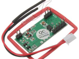
Description
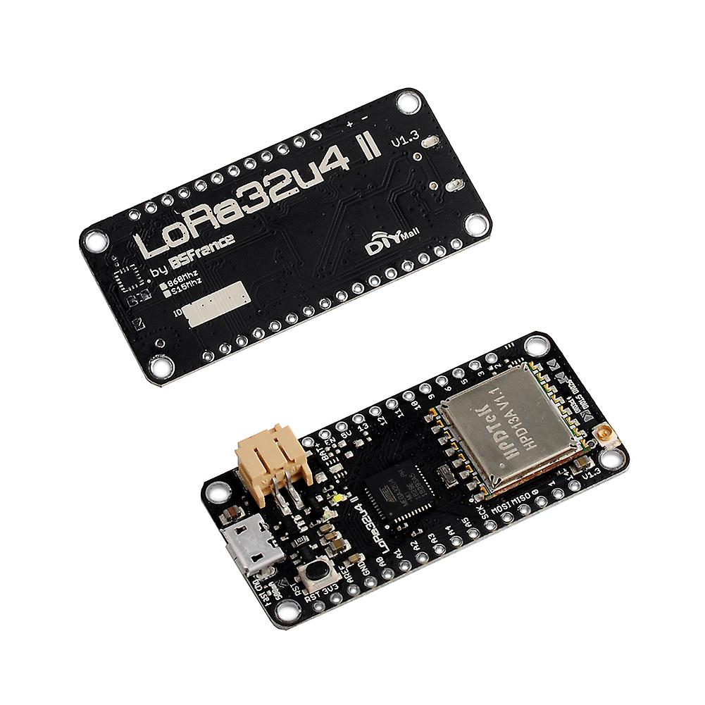
LoRa32u4 II is a light and low consumption board based on the Atmega32u4 and HPD13 868MHz LoRA module and an USB battery charging circuit. Ideal for creating long range wireless networks that can exceed 2.4GHz 802.15.4 and similar, it is more flexible than Bluetooth LE, does not require high power unlike WiFi and offers long range.
Arduino IDE Setup
The first thing you will need to do is to download the latest release of the Arduino IDE. You will need to be using version 1.8 or higher for this guide
After you have downloaded and installed the latest version of Arduino IDE, you will need to start the IDE and navigate to the Preferences menu. You can access it from the File menu in Windows or Linux, or the Arduino menu on OS X.

A dialog will pop up just like the one shown below.

We will only need to add one URL to the IDE in this example, but you can add multiple URLS by separating them with commas. Copy and paste the link below into the Additional Boards Manager URLs option in the Arduino IDE preferences.
https://adafruit.github.io/arduino-board-index/package_adafruit_index.json

Using with Arduino IDE
Since the Feather 32u4 uses an ATmega32u4 chip running at 8 MHz, you can pretty easily get it working with the Arduino IDE. Many libraries (including the popular ones like NeoPixels and display) work great with the ’32u4 and 8 MHz clock speed.
Now that you have added the appropriate URLs to the Arduino IDE preferences, you can open the Boards Manager by navigating to the Tools->Board menu.

Once the Board Manager opens, click on the category drop down menu on the top left hand side of the window and select Contributed.

You will then be able to select and install the boards supplied by the URLs added to the preferences. In the example below, we are installing support for Adafruit AVR Boards, but the same applies to all boards installed with the Board Manager.

Next, close and reopen the Arduino IDE to ensure that all of the boards are properly installed. You should now be able to select and upload to the new boards listed in the Tools->Board menu.

Blink
Now you can upload your first blink sketch!
Plug in the Feather 32u4 and wait for it to be recognized by the OS (just takes a few seconds). It will create a serial/COM port, you can now select it from the dropdown, it’ll even be ‘indicated’ as Feather 32u4!

Now load up the Blink example code
void setup() {
// initialize digital pin 13 as an output.
pinMode(13, OUTPUT);
}
// the loop function runs over and over again forever
void loop() {
digitalWrite(13, HIGH); // turn the LED on (HIGH is the voltage level)
delay(1000); // wait for a second
digitalWrite(13, LOW); // turn the LED off by making the voltage LOW
delay(1000); // wait for a second
}
And click upload! That’s it, you will be able to see the LED blink
Using the RFM9X Radio
Before beginning make sure you have your Feather working smoothly, it will make this part a lot easier. Once you have the basic Feather functionality going – you can upload code, blink an LED, use the serial output, etc. you can then upgrade to using the radio itself.
Note that the sub-GHz radio is not designed for streaming audio or video! It’s best used for small packets of data. The data rate is adjustbale but its common to stick to around 19.2 Kbps (thats bits per second). Lower data rates will be more successful in their transmissions
You will, of course, need at least two paired radios to do any testing! The radios must be matched in frequency (e.g. 900 MHz & 900 MHz are ok, 900 MHz & 433 MHz are not). They also must use the same encoding schemes, you cannot have a 900 MHz RFM69 packet radio talk to a 900 MHz RFM96 LoRa radio.
Arduino Library
To begin talking to the radio, you will need to download the RadioHead library. You can do that by visiting the github repo and manually downloading or, easier, just click this button to download the zip corresponding to version 1.62. Note that while all the code in the examples below are based on this version
Uncompress the zip and find the folder named RadioHead and check that the RadioHead folder contains RH_RF95.cpp and RH_RF95.h (as well as a few dozen other files for radios that are supported)
Place the RadioHead library folder your arduinosketchfolder/libraries/ folder.
You may need to create the libraries subfolder if its your first library. Restart the IDE.
Basic RX & TX example
Lets get a basic demo going, where one Feather transmits and the other receives. We’ll start by setting up the transmitter.
Transmitter example code
This code will send a small packet of data once a second to node address #1
Load this code into your Transmitter Arduino/Feather!
// Feather9x_TX
// -*- mode: C++ -*-
// Example sketch showing how to create a simple messaging client (transmitter)
// with the RH_RF95 class. RH_RF95 class does not provide for addressing or
// reliability, so you should only use RH_RF95 if you do not need the higher
// level messaging abilities.
// It is designed to work with the other example Feather9x_RX
#include <SPI.h>
#include <RH_RF95.h>
#define RFM95_CS 8
#define RFM95_RST 4
#define RFM95_INT 7
// Change to 434.0 or other frequency, must match RX’s freq!
#define RF95_FREQ 915.0
// Singleton instance of the radio driver
RH_RF95 rf95(RFM95_CS, RFM95_INT);
void setup()
{
pinMode(RFM95_RST, OUTPUT);
digitalWrite(RFM95_RST, HIGH);
Serial.begin(115200);
while (!Serial) {
delay(1);
}
delay(100);
Serial.println(“Feather LoRa TX Test!”);
// manual reset
digitalWrite(RFM95_RST, LOW);
delay(10);
digitalWrite(RFM95_RST, HIGH);
delay(10);
while (!rf95.init()) {
Serial.println(“LoRa radio init failed”);
Serial.println(“Uncomment ‘#define SERIAL_DEBUG’ in RH_RF95.cpp for detailed debug info”);
while (1);
}
Serial.println(“LoRa radio init OK!”);
// Defaults after init are 434.0MHz, modulation GFSK_Rb250Fd250, +13dbM
if (!rf95.setFrequency(RF95_FREQ)) {
Serial.println(“setFrequency failed”);
while (1);
}
Serial.print(“Set Freq to: “); Serial.println(RF95_FREQ);
// Defaults after init are 434.0MHz, 13dBm, Bw = 125 kHz, Cr = 4/5, Sf = 128chips/symbol, CRC on
// The default transmitter power is 13dBm, using PA_BOOST.
// If you are using RFM95/96/97/98 modules which uses the PA_BOOST transmitter pin, then
// you can set transmitter powers from 5 to 23 dBm:
rf95.setTxPower(23, false);
}
int16_t packetnum = 0; // packet counter, we increment per xmission
void loop()
{
delay(1000); // Wait 1 second between transmits, could also ‘sleep’ here!
Serial.println(“Transmitting…”); // Send a message to rf95_server
char radiopacket[20] = “Hello World # “;
itoa(packetnum++, radiopacket+13, 10);
Serial.print(“Sending “); Serial.println(radiopacket);
radiopacket[19] = 0;
Serial.println(“Sending…”);
delay(10);
rf95.send((uint8_t *)radiopacket, 20);
Serial.println(“Waiting for packet to complete…”);
delay(10);
rf95.waitPacketSent();
// Now wait for a reply
uint8_t buf[RH_RF95_MAX_MESSAGE_LEN];
uint8_t len = sizeof(buf);
Serial.println(“Waiting for reply…”);
if (rf95.waitAvailableTimeout(1000))
{
// Should be a reply message for us now
if (rf95.recv(buf, &len))
{
Serial.print(“Got reply: “);
Serial.println((char*)buf);
Serial.print(“RSSI: “);
Serial.println(rf95.lastRssi(), DEC);
}
else
{
Serial.println(“Receive failed”);
}
}
else
{
Serial.println(“No reply, is there a listener around?”);
}
}
Once uploaded you should see the following on the serial console

Now open up another instance of the Arduino IDE – this is so you can see the serial console output from the TX Feather while you set up the RX Feather.
Receiver example code
This code will receive and acknowledge a small packet of data.
Load this code into your Receiver Arduino/Feather!
Make sure the #define RF95_FREQ 915.0 matches your transmitter Feather!
// Feather9x_RX
// -*- mode: C++ -*-
// Example sketch showing how to create a simple messaging client (receiver)
// with the RH_RF95 class. RH_RF95 class does not provide for addressing or
// reliability, so you should only use RH_RF95 if you do not need the higher
// level messaging abilities.
// It is designed to work with the other example Feather9x_TX
#include <SPI.h>
#include <RH_RF95.h>
#define RFM95_CS 8
#define RFM95_RST 4
#define RFM95_INT 7
// Change to 434.0 or other frequency, must match RX’s freq!
#define RF95_FREQ 915.0
// Singleton instance of the radio driver
RH_RF95 rf95(RFM95_CS, RFM95_INT);
// Blinky on receipt
#define LED 13
void setup()
{
pinMode(LED, OUTPUT);
pinMode(RFM95_RST, OUTPUT);
digitalWrite(RFM95_RST, HIGH);
Serial.begin(115200);
while (!Serial) {
delay(1);
}
delay(100);
Serial.println(“Feather LoRa RX Test!”);
// manual reset
digitalWrite(RFM95_RST, LOW);
delay(10);
digitalWrite(RFM95_RST, HIGH);
delay(10);
while (!rf95.init()) {
Serial.println(“LoRa radio init failed”);
Serial.println(“Uncomment ‘#define SERIAL_DEBUG’ in RH_RF95.cpp for detailed debug info”);
while (1);
}
Serial.println(“LoRa radio init OK!”);
// Defaults after init are 434.0MHz, modulation GFSK_Rb250Fd250, +13dbM
if (!rf95.setFrequency(RF95_FREQ)) {
Serial.println(“setFrequency failed”);
while (1);
}
Serial.print(“Set Freq to: “); Serial.println(RF95_FREQ);
// Defaults after init are 434.0MHz, 13dBm, Bw = 125 kHz, Cr = 4/5, Sf = 128chips/symbol, CRC on
// The default transmitter power is 13dBm, using PA_BOOST.
// If you are using RFM95/96/97/98 modules which uses the PA_BOOST transmitter pin, then
// you can set transmitter powers from 5 to 23 dBm:
rf95.setTxPower(23, false);
}
void loop()
{
if (rf95.available())
{
// Should be a message for us now
uint8_t buf[RH_RF95_MAX_MESSAGE_LEN];
uint8_t len = sizeof(buf);
if (rf95.recv(buf, &len))
{
digitalWrite(LED, HIGH);
RH_RF95::printBuffer(“Received: “, buf, len);
Serial.print(“Got: “);
Serial.println((char*)buf);
Serial.print(“RSSI: “);
Serial.println(rf95.lastRssi(), DEC);
// Send a reply
uint8_t data[] = “And hello back to you”;
rf95.send(data, sizeof(data));
rf95.waitPacketSent();
Serial.println(“Sent a reply”);
digitalWrite(LED, LOW);
}
else
{
Serial.println(“Receive failed”);
}
}
}
Now open up the Serial console on the receiver, while also checking in on the transmitter’s serial console. You should see the receiver is…well, receiving packets

You can see that the library example prints out the hex-bytes received 48 65 6C 6C 6F 20 57 6F 72 6C 64 20 23 30 0 20 20 20 20 0, as well as the ASCII ‘string’ Hello World. Then it will send a reply.
And, on the transmitter side, it is now printing that it got a reply after each transmisssion And hello back to you because it got a reply from the receiver.

For more details click here

