Description
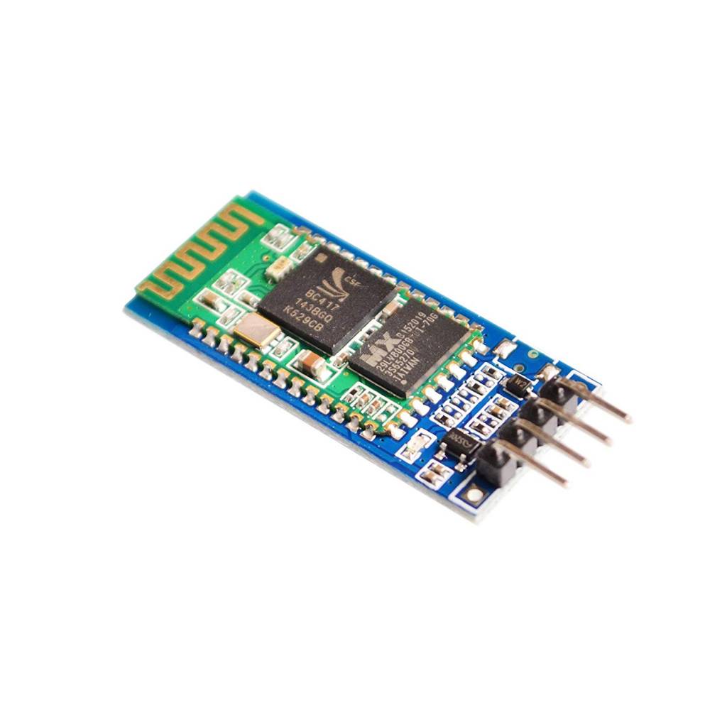
Allows your device to both send or receive the TTL data via Bluetooth technology without connecting a serial cable to your computer.
This bluetooth bluetooth is perfect for adding bluetooth functionality to your arduino project. But don’t think that it is limited to just being used there. Another use you will find for this bluetooth module is with your flight management controller on your quadcopter.
It should be able to be used with several of the available options, so long as the control software supports bluetooth functionality. With this module, you don’t have to plug into your flight controller with a micro usb cable every time you want to tweak something, upload a new configuration, or check data.
So long as you are within range,youI can connect to it through bluetooth instead.
There is even an android version of your flight controller software so you can do everything from your phone and not have to carry a laptop with you. Do some googling and you should also be able to find instructions and how-to’s for changing the settings on the bluetooth module itself, like the name it uses to identify itself and the pass code for pairing it with devices, along with enabling and disabling different bluetooth protocols.
Note:
1.SPP-CA Bluetooth module serial port level to 3.3V, if connect 5V level,the system needs to increase the level conversion chip.
2.The Bluetooth signal is greatly affected by the surrounding, such as trees, metals, walls and other obstacles will have a certain Bluetooth signal absorption or shielding, we advise do not installed in the metal shell.
3.Due to the metal will weaken the antenna function,we advise when you lay board for the module, the module below the antenna do not shop and alignment, it is best to hollow out.
- Works with any USB Bluetooth adapters, running in slave role: Pair with BT dongle and master module. Led indicate Bluetooth connection status, flashing Bluetooth connectivity, lit the Bluetooth connection and open a port Backplane
- Core module uses HC-06, leads from the module interface includes VCC, GND, TXD, RXD, reserve LED status output pin, the microcontroller can be judged by the foot state Bluetooth has connected KEY pin slave invalid.
- Small size, low power consumption,high sensitivity for send and receive. Bluetooth version: V2.0+EDR &Operating voltage: 3.3V &Host Interface:UART &Storage Temperature:-40℃~+150℃&Signal coverage: 30ft &Item size: 4.3 * 1.6 * 0.7cm &Item weight: 3g.
- The module is mainly used for short-range data wireless transmission,such as Bluetooth wireless data transmission,Industrial remote control, telemetry,Traffic, underground positioning, alarm,Smart home ect.
- Industrial serial port bluetooth, Drop-in replacement for wired serial connections, transparent usage. You can use it simply for a serial port replacement to establish connection between MCU and GPS, PC to your embedded project and etc. Computer and peripheral devices.
Getting started with the HC-06 Wireless Slave Bluetooth Module
This tutorial will explain how to setup communications between an Arduino and a Bluetooth device running serial terminal software – in this case an Android smartphone. Please note that the Bluetooth module used in this tutorial is not compatible with iOS devices .
Our end goal is to control a digital output pin on the Arduino by sending text commands from the smartphone, and also sending text from the Arduino back to the smartphone.
Hardware required
Connecting the Hardware
The connections are very simple:
Arduino <—> Bluetooth Module
- 5V to Vcc
- GND to GND
- D0 to TX
- D1 to RX

in this step. Once the Bluetooth module has been connected and power applied, the LED will blink rapidly. This means that it has not been “paired” with another Bluetooth device. The LED stays on continuously when paired.
Software (Arduino and HC-06)

Tap the HC06 in the list, and you will then be asked for the PIN – it is 1234. Finally, open your terminal app on the smartphone, and select “Connect a device” from the app menu. Select the HC-06 option and then wait a moment. The LED on the Bluetooth module should stay on and the app will show “connected: HC-06” .
Once you have connected the hardware, enter the sketch below into the Arduino IDE and upload it to your board.
CODE
#include <SoftwareSerial.h>
SoftwareSerial BT(10, 11);
// creates a “virtual” serial port/UART
// connect BT module TX to D10
// connect BT module RX to D11
// connect BT Vcc to 5V, GND to GND
void setup()
{
// set digital pin to control as an output
pinMode(13, OUTPUT);
// set the data rate for the SoftwareSerial port
BT.begin(9600);
// Send test message to other device
BT.println(“Hello from Arduino”);
}
char a; // stores incoming character from other device
void loop()
{
if (BT.available())
// if text arrived in from BT serial…
{
a=(BT.read());
if (a==’0′)
{
digitalWrite(13, HIGH);
BT.println(“LED on”);
}
if (a==’1′)
{
digitalWrite(13, LOW);
BT.println(“LED off”);
}
if (a==’?’)
{
BT.println(“Send ‘0’ to turn LED on”);
BT.println(“Send ‘1’ to turn LED off”);
}
// you can add more “if” statements with other characters to add more commands
}
}
You can see in line two of the sketch that the software serial port has been defined with the name “BT”, and that any references to the module for serial communication in the sketch are now BT.begin, BT.println and so on.
The sketch waits for a character of text to be sent from the Bluetooth module to the software serial port, and this is stored in the variable char a at line 22. This is then interrogated using the if functions starting from line 23.
You can see how simple it is for the Arduino to take action based on the character received – but where does this text come from? In our demonstration we’ll use terminal emulation software on the Android smartphone.

Now send the number 0 through the terminal and the onboard LED on the Arduino should turn on.

Send 1 and it should turn off. The Arduino will also respond and send the status back to the app.


