Description
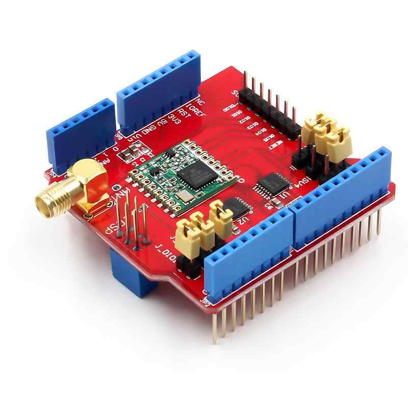
The LoRa Shield is a long-range transceiver on an Arduino shield form factor and based on Open source library. The Lora Shield allows the user to send data and reach extremely long ranges at low data-rates. It provides ultra-long range spread spectrum communication and high interference immunity whilst minimising current consumption.
The LoRa Shield based on RFM95W/RFM98W targets professional wireless sensor network applications such as irrigation systems, smart metering, smart cities, smartphone detection, building automation, and so on.
Using Hope RF’s patented LoRaTM modulation technique the Lora Shield can achieve a sensitivity of over -148dBm using a low-cost crystal and bill of materials. The high sensitivity combined with the integrated +20 dBm power amplifier yields industry leading link budget making it optimal for any application requiring range or robustness. LoRaTM also provides significant advantages in both blocking and selectivity over conventional modulation techniques, solving the traditional design compromise between range, interference immunity and energy consumption.
These devices also support high performance (G) FSK modes for systems including WMBus, IEEE802.15.4g. The Lora Shield deliver exceptional phase noise, selectivity, receiver linearity and IIP3 for significantly lower current consumption than competing devices.
FEATURES:
- Compatible with 3.3v or 5v I/O Arduino Board.
- Frequency Band: 915 MHZ(Pre-configure in factory)
- Low power consumption
- Compatible with Arduino Leonardo, Uno, Mega, DUE
- External Antenna via I-Pex connector
SPECIFICATIONS
- 168 dB maximum link budget.
- +20 dBm – 100 mW constant RF output vs.
- +14 dBm high efficiency PA.
- Programmable bit rate up to 300 kbps.
- High sensitivity: down to -148 dBm.
- Bullet-proof front end: IIP3 = -12.5 dBm.
- Excellent blocking immunity.
- Low RX current of 10.3 mA, 200 nA register retention.
- Fully integrated synthesizer with a resolution of 61 Hz.
- FSK, GFSK, MSK, GMSK, LoRaTM and OOK modulation.
- Built-in bit synchronizer for clock recovery.
- Preamble detection.
- 127 dB Dynamic Range RSSI.
- Automatic RF Sense and CAD with ultra-fast AFC.
- Packet engine up to 256 bytes with CRC.
- Built-in temperature sensor and low battery indicator.
Getting started with the Arduino Shield featuring LoRa 868 MHz
In this example,we use two LoRa Shields to transmit and receive signal, there are some project in the RadioHead Library,the operation is as follows
Hardware required
- Arduino UNO x2
- LoRa 915 MHz x2
Interfacing LoRa 868 MHz with Arduino UNO
Connect two LoRa Shields with Arduino board and connect them to computer via the USB cable; We used the LoRa Shield + Arduino UNO as the server to transmit signal and the LoRa Shield + Arduino UNO as the client to receive signal here.
Begin by carefully starting the rear connector of the Lora shield onto the Arduino UNO. Go slowly and ensure that all pins are inserted correctly and are straight.


Remember! You need to make two of these circuits. One acts as a Server and the other as a Client. The wiring for both is identical. Once you have everything hooked up you are ready to go!
Use the RadioHead Library With Arduino Boards
The RadioHead Library simplifies communication between the Arduino Board and the LoRa Shield. We can find it here . To use it in your project you just have to copy it in your Arduino project folder (next to your main Arduino project file .ino).
Compile Notice:
- Check if you have set the right frequency:After putting the library in the right place, you have to also modify the frequency to the frequency you want to use, the position of this is setFrequency() in the file: arduinolibrariesRadioHeadRH_RF95.cpp;
- The RF95-server sketch use the led=9 to show the status. please change it to other LED , such 8. because 9 is connected to the LoRa module’s RESET pin. you will see ‘init fail’ in the default server sketch.
Upload the sample sketch
1st Arduino Uno: Open the sample sketch that is located in file>examples>RadioHead>rf95>rf_server. As shown below

2nd Arduino Uno: Open the sample sketch that is located in file>examples>RadioHead>rf95>rf_client. As show below

After configure the IDE settings, upload the sketch to Arduino. Check the Serial monitor and we can view the running result of the two boards.
1.Running result of Server

2.Running result of Client


Reviews
There are no reviews yet.