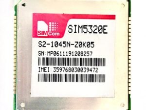
Description
| Dimensions and weight | |
|---|---|
| Dimensions | 1.77 in x 1.77 in x 0.59 in (4.5 cm x 4.5 cm x 1.5 cm) |
| Weight |
0.68 oz (19.3g)
|
Getting started with the A6 GPRS Pro Series GSM GPRS core module
In this Tutorials we are going to deal with A6 GPRS Pro Series GSM GPRS core module this is simple and easy to connect with Arduino
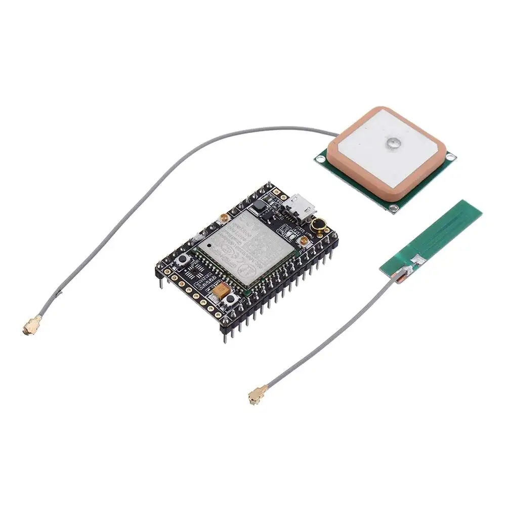
Step1: Hardware required
Step2: Connecting the Hardware
To start with, connect U_TxD and U_RxD pin on module to digital pin#2 and #4 on Arduino as we’ll be using software serial to talk to the module.
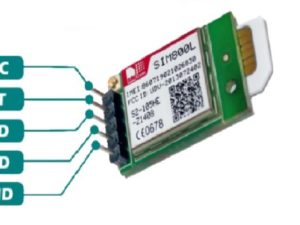
| A6 GPRS | Arduino UNO |
| U_TxD | D2 |
| U_RxD | D4 |
| VCC | VCC 5V |
| GND | GND |
Finally, connect the antenna, insert fully activated Micro SIM card in the socket.
Step3: Arduino Code – Testing AT Commands
For sending AT commands and communicating with the A6 module, we will use the serial monitor. The sketch below will enable the Arduino to communicate with the A6 module on serial monitor. Before we proceed with detailed breakdown of code, connect your Arduino to PC, compile below code and upload it to the Arduino.
Once you open a serial monitor, make sure that ‘Both NL & CR’ option is selected!
CODE
#include <SoftwareSerial.h>
//Create software serial object to communicate with A6
SoftwareSerial mySerial(2, 4); //A6 Tx & Rx is connected to Arduino #2 & #4
void setup()
{
//Begin serial communication with Arduino and Arduino IDE (Serial Monitor)
Serial.begin(9600);
//Begin serial communication with Arduino and A6
mySerial.begin(9600);
Serial.println(“Initializing…”);
delay(1000);
mySerial.println(“AT”); //Once the handshake test is successful, it will back to OK
updateSerial();
mySerial.println(“AT+CSQ”); //Signal quality test, value range is 0-31 , 31 is the best
updateSerial();
mySerial.println(“AT+CCID”); //Read SIM information to confirm whether the SIM is plugged
updateSerial();
mySerial.println(“AT+CREG?”); //Check whether it has registered in the network
updateSerial();
}
void loop()
{
updateSerial();
}
void updateSerial()
{
delay(500);
while (Serial.available())
{
mySerial.write(Serial.read());//Forward what Serial received to Software Serial Port
}
while(mySerial.available())
{
Serial.write(mySerial.read());//Forward what Software Serial received to Serial Port
}
}
Testing the circuit
open your serial monitor by clicking on the icon in the right top corner(like search icon)

Now that we have established a basic connection, we will try to communicate with the A6 module by sending AT commands.
AT – It is the most basic AT command. It also initializes Auto-baud’er. If it works you should see the AT characters echo and then OK, telling you it’s OK and it’s understanding you correctly! You can then send some commands to query the module and get information about it such as
AT+CSQ – Check the ‘signal strength’ – the first # is dB strength, it should be higher than around 5. Higher is better. Of course it depends on your antenna and location!
AT+CCID – get the SIM card number – this tests that the SIM card is found OK and you can verify the number is written on the card.
AT+CREG? Check that you’re registered on the network. The second # should be 1 or 5. 1 indicates you are registered to home network and 5 indicates roaming network. Other than these two numbers indicate you are not registered to any network.
Arduino Code – Sending SMS
Let’s move on to the interesting stuff. Let’s program our Arduino to send an SMS to any phone number you wish. Before trying the sketch out, you need to enter the phone number. Search for the string ZZxxxxxxxxxx and replace ZZ with county code and xxxxxxxxxx with the 10 digit phone number.
#include <SoftwareSerial.h>

//Create software serial object to communicate with A6
SoftwareSerial mySerial(2, 4); //A6 Tx & Rx is connected to Arduino #2 & #4

void setup()
{
//Begin serial communication with Arduino and Arduino IDE (Serial Monitor)
Serial.begin(9600);

//Begin serial communication with Arduino and A6
mySerial.begin(9600);

Serial.println("Initializing...");
delay(1000);

mySerial.println("AT"); //Once the handshake test is successful, it will back to OK
updateSerial();

mySerial.println("AT+CMGF=1"); // Configuring TEXT mode
updateSerial();
mySerial.println("AT+CMGS=\"+ZZXXXXXXXXXXX\"");//change ZZ with country code and xxxxxxxxxxx with phone number to sms
updateSerial();
mySerial.print("Faranux Electronics LTD | faranux.com"); //text content
updateSerial();
mySerial.write(26);
}

void loop()
{
}

void updateSerial()
{
delay(500);
while (Serial.available())
{
mySerial.write(Serial.read());//Forward what Serial received to Software Serial Port
}
while(mySerial.available())
{
Serial.write(mySerial.read());//Forward what Software Serial received to Serial Port
}
}
Arduino Code – Reading SMS
Now let’s program our Arduino to read incoming messages. This sketch is very useful when you need to trigger an action when a specific SMS is received. For example, when the Arduino receives an SMS, you can instruct it to turn on or off a relay. You got the idea!
#include <SoftwareSerial.h>
//Create software serial object to communicate with A6
SoftwareSerial mySerial(3, 2); //A6 Tx & Rx is connected to Arduino #3 & #2
void setup()
{
//Begin serial communication with Arduino and Arduino IDE (Serial Monitor)
Serial.begin(9600);
//Begin serial communication with Arduino and A6
mySerial.begin(9600);
Serial.println(“Initializing…”);
delay(1000);
mySerial.println(“AT”); //Once the handshake test is successful, it will back to OK
updateSerial();
mySerial.println(“AT+CMGF=1”); // Configuring TEXT mode
updateSerial();
mySerial.println(“AT+CNMI=1,2,0,0,0”); // Decides how newly arrived SMS messages should be handled
updateSerial();
}
void loop()
{
updateSerial();
}
void updateSerial()
{
delay(500);
while (Serial.available())
{
mySerial.write(Serial.read());//Forward what Serial received to Software Serial Port
}
while(mySerial.available())
{
Serial.write(mySerial.read());//Forward what Software Serial received to Serial Port
}
}
Results
Once you send the SMS to A6 GSM module, you will see below output on serial monitor.

NOTE: While communicating with serial devices via Arduino, sometimes Arduino do not receive or send complete messages, especially when we communicate with LCDs or with GSM. While reading SMS via GSM Module, Arduino does not retrieve complete message because Serial buffer is full as the buffer length of Arduino is limited to 64 bytes only.
The simplest solution to this is to increase the size of the SoftwareSerial buffer from its default size of 64 bytes to 512 bytes (or smaller, depending on what works for you).
On a Windows PC, go to C:\Program Files (x86) -> Arduino -> hardware -> Arduino -> avr -> libraries -> SoftwareSerial (-> src for newer version of Arduino IDE) Open SoftwareSerial.h and change the line:
// RX buffer size
#define _SS_MAX_RX_BUFF 64
The first is to download notepad ++ so you can edit and save this file (SoftwareSerial.h) by using notepad++.

to
// RX buffer size
#define _SS_MAX_RX_BUFF 512

Save the file and try your sketch again.
Arduino Code – Making Call
Now let’s program our Arduino to make call. This sketch is very useful when you want your Arduino to make an SOS/distress call in case of emergency like temperature being exceeded or someone breaks into your house. You got the idea!
Before trying the sketch out, you need to enter the phone number. Search for the string ZZxxxxxxxxxx and replace ZZ with county code and xxxxxxxxxx with the 10 digit phone number.
#include <SoftwareSerial.h>
//Create software serial object to communicate with A6
SoftwareSerial mySerial(3, 2); //A6 Tx & Rx is connected to Arduino #3 & #2
void setup()
{
//Begin serial communication with Arduino and Arduino IDE (Serial Monitor)
Serial.begin(9600);
//Begin serial communication with Arduino and A6
mySerial.begin(9600);
Serial.println(“Initializing…”);
delay(1000);
mySerial.println(“AT”); //Once the handshake test is successful, i t will back to OK
updateSerial();
mySerial.println(“ATD+ZZxxxxxxxxxx”); // change ZZ with country code and xxxxxxxxxxx with phone number to dial
updateSerial();
delay(20000); // wait for 20 seconds…
mySerial.println(“ATH”); //hang up
updateSerial();
}
void loop()
{
}
void updateSerial()
{
delay(500);
while (Serial.available())
{
mySerial.write(Serial.read());//Forward what Serial received to Software Serial Port
}
while(mySerial.available())
{
Serial.write(mySerial.read());//Forward what Software Serial received to Serial Port
}
}