Description
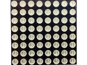
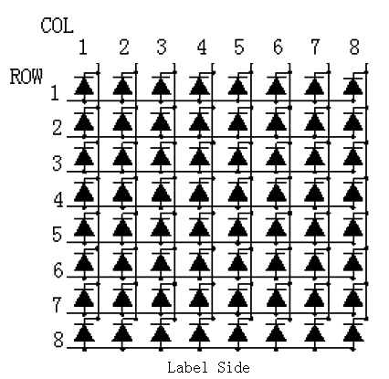
8*8 Mini Dot Matrix LED Display Red Common Anode consists of 64 dots or pixels. There is a LED for each pixel and these LEDs are connected to total of 16 pin. The one with a label ending with BS is a common Anode dot matrix.
About 8×8 LED Matrix
With low-voltage scanning, 8×8 LED Matrix LED display have advantages such as power saving, long service life, low cost, high brightness, a wide angle of view, long visual range, waterproofness, and so on. They can meet the needs of different applications and thus have a broad development prospect.
Getting started with the 8*8 Mini Dot Matrix LED Display Red Common Cathode Digital Tube 16-pin
In this lesson we are going to interface a single color 8×8 LED matrix with Arduino and display a few characters to experience its charm from the beginning.
Hardware required
- Arduino UNO
- 8*8 Mini Dot Matrix LED Display Red Common Anode
- Breadboard
- Jumper wires
Connecting the Hardware
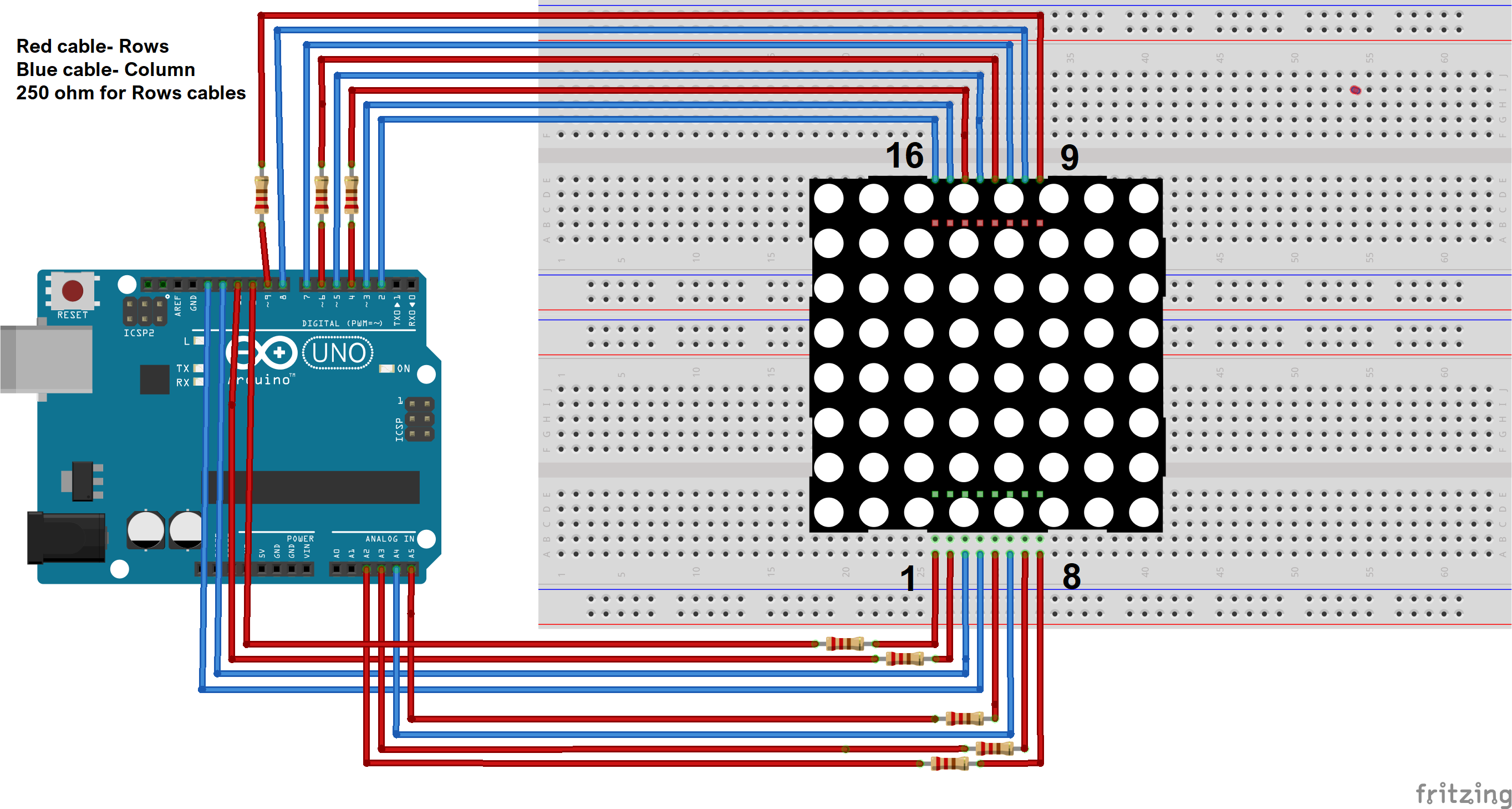
You can identify the pin out diagram of it using the following figure.
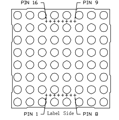
Below is the internal structure. You can see that in the common Anode dot matrix, ROW is the anode of LED and COL is the cathode.
Here’s a matrix of the pin connections, based on the diagram above:
| Matrix pin no. | Row | Column | Arduino pin number |
| 1 | 5 | – | 13 |
| 2 | 7 | – | 12 |
| 3 | – | 2 | 11 |
| 4 | – | 3 | 10 |
| 5 | 8 | – | 16 (analog pin 2) |
| 6 | – | 5 | 17 (analog pin 3) |
| 7 | 6 | – | 18 (analog pin 4) |
| 8 | 3 | – | 19 (analog pin 5) |
| 9 | 1 | – | 2 |
| 10 | – | 4 | 3 |
| 11 | – | 6 | 4 |
| 12 | 4 | – | 5 |
| 13 | – | 1 | 6 |
| 14 | 2 | – | 7 |
| 15 | – | 7 | 8 |
| 16 | – | 8 | 9 |
Since the wiring of this experiment is a little complicated, we need to do it step by step.
Upload the sample sketch
Copy the example code below into an Arduino program.
int R[] = {2,7,A5,5,13,A4,12,A2};
// 2-dimensional array of column pin numbers:
int C[] = {6,11,10,3,A3,4,8,9};
unsigned char biglove[8][8] = //the big “heart”
{
0,0,0,0,0,0,0,0,
0,1,1,0,0,1,1,0,
1,1,1,1,1,1,1,1,
1,1,1,1,1,1,1,1,
1,1,1,1,1,1,1,1,
0,1,1,1,1,1,1,0,
0,0,1,1,1,1,0,0,
0,0,0,1,1,0,0,0,
};
unsigned char smalllove[8][8] = //the small “heart”
{
0,0,0,0,0,0,0,0,
0,0,0,0,0,0,0,0,
0,0,1,0,0,1,0,0,
0,1,1,1,1,1,1,0,
0,1,1,1,1,1,1,0,
0,0,1,1,1,1,0,0,
0,0,0,1,1,0,0,0,
0,0,0,0,0,0,0,0,
};
void setup()
{
// iterate over the pins:
for(int i = 0;i<8;i++)
// initialize the output pins:
{
pinMode(R[i],OUTPUT);
pinMode(C[i],OUTPUT);
}
}
void loop()
{
for(int i = 0 ; i < 100 ; i++) //Loop display 100 times
{
Display(biglove); //Display the “Big Heart”
}
for(int i = 0 ; i < 50 ; i++) //Loop display 50 times
{
Display(smalllove); //Display the “small Heart”
}
}
void Display(unsigned char dat[8][8])
{
for(int c = 0; c<8;c++)
{
digitalWrite(C[c],LOW);//use thr column
//loop
for(int r = 0;r<8;r++)
{
digitalWrite(R[r],dat[r][c]);
}
delay(1);
Clear(); //Remove empty display light
}
}
void Clear()
{
for(int i = 0;i<8;i++)
{
digitalWrite(R[i],LOW);
digitalWrite(C[i],HIGH);
}
}
Running Result
A few seconds after the upload finishes, you should now see a heart blink on the 8×8 LED matrix as shown below.