Description
This board is low cost Minimum System Development Board for ARM Microcontroller – STM32F103C8T6. Board is suitable for learners that want to learn STM32 microcontroller with ARM Coretex-M3 32-bit core.
Features
- On-board Mini USB interface, you can give the board power supply and USB communication.
- On-board test indicator LED
- On-board reset button and power indicator LED
- On-board 100ma 3.3V Regulator
- All GPIO are led out and the names of the pins are marked
- After soldering the headers, you can directly plug the board onto the breadboard
Getting Started with STM32F103C8T6
In this tutorial, we will take a quick look at the STM32F103C8T6 Development Board, which is based on an ARM Cortex-M3 Microcontroller from STMicroelectronics. We will see some important features of this board, how to configure your existing Arduino environment to work with this board and also write the first program. So, let’s get started.
Hardware Required:
- STM32F103C8T6 based STM32 Blue Pill Development Board
- USB to Serial Converter Module (FTDI Programmer)
- Jumper wires
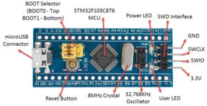
The following image shows the front side parts of a typical STM32 Blue Pill Board. As you can see, the layout of the board is very simple and some might even confuse it for an Arduino Nano.
Coming to the Blue Pill board itself, you get the board and two male header strips for you to solder on to the board (shame that they don’t came pre-soldered).
The other features of the board are as follows:
- It contains the main MCU – the STM32F103C8T6 in a Quad Flat Package.
- A Reset Switch – to reset the Microcontroller.
- microUSB port – for serial communication and power.
- BOOT Selector Jumpers – BOOT0 and BOOT1 jumpers for selecting the booting memory.
- Two LEDs – User LED and Power LED.
- 8 MHz Crystal – Main Clock for MCU.
- 32.768KHz Oscillator – RTC Clock.
- SWD Interface – for programming and debugging using ST-Link.
- 3.3V regulator (on the bottom) – converts 5V to 3.3V for powering the MCU.
On either long edge of the board, there are pins for connecting various Analog and Digital IO and Power related stuff. The following image shows the pin configuration of the board along with different functions supported by each pin.
As you can see from the above image, each pin of the STM32F103C8T6 MCU can have multiple functions (but only one has to be selected). Also, note that some IO pins are 5V tolerant, which means that you can connect 5V compatible IO on those pins without any worry.
How to Use the BOOT Pins?
The BOOT0 and BOOT1 pins of the MCU are used to select the memory from which it boots. The following image shows three different options of boot spaces based on these pins.
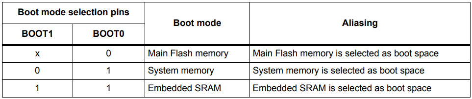
When both BOOT0 and BOOT1 pins are LOW, then the internal Flash Memory acts as the main boot space and when BOOT0 is HIGH and BOOT1 is LOW, the System Memory acts as the main boot space. These two options are important for us.
To upload the code to the Flash Memory of the MCU, you have to select System Memory as the main boot space. The reason for this is that the System Memory contains the embedded bootloader, which is programmed during the production itself by STMicroelectronics.
By booting into the System Memory i.e. the bootloader ROM, you can reprogram the Flash Memory with your application using USART1 Serial Interface.
Once the program is uploaded to the Flash Memory, you can switch back the BOOT0 to LOW, so that from next reset or power-up onwards, the MCU will boot from the Flash Memory. If you notice, in both the cases i.e. selecting Flash Memory and selecting System Memory as boot spaces, the BOOT1 pin is LOW. Only the BOOT0 is toggled between LOW (Flash Memory) and HIGH (System Memory).
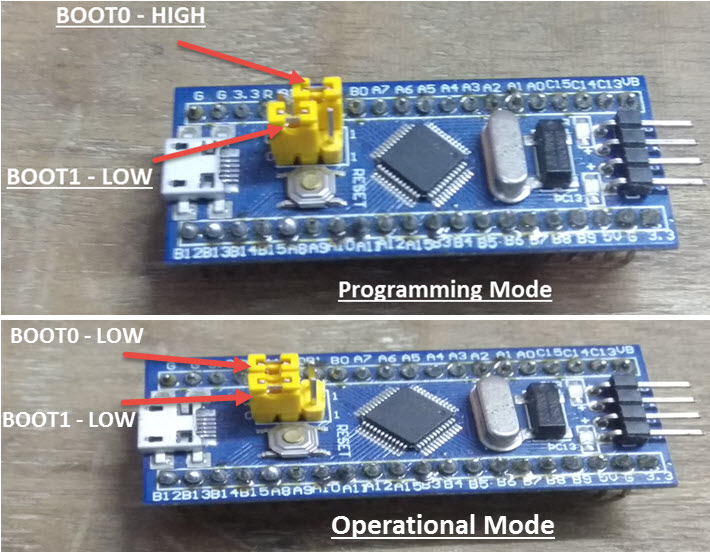
For the sake of convenience, let us call these BOOT selections as Programming Mode and Operational Mode. For Programming Mode, the BOOT0 pin is made HIGH and for Operational Mode, the BOOT0 pin is made LOW (default). In both the modes, the BOOT1 pin stays LOW.
Connecting the Hardware
Since this is our introduction part and all we will be doing is Blink an LED (which is already present on the board), we don’t need much hardware with respect to the project and the MCU. But for programming the Microcontroller, we need a USB to Serial Converter Module, like an FTDI board (or anything similar). As mentioned in the BOOT Pins section, the bootloader can be accessed using USART1 pins of the Microcontroller to program the Flash Memory. And for the MCU to communicate with the USART1, we need a USB to Serial Converter.
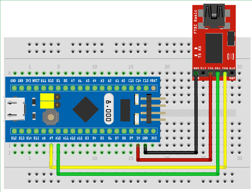
Connections
The connections should be as follows:
- STM32 Blue Pill – FTDI Programmer
- 5V – VCC
- GND – GND
- A9 – RX
- A10 – TX
Configuring Arduino IDE to Program STM32F103C8T6 Blue Pill
I am sure you already have Arduino IDE installed on your PC (or Laptop). If not, then install it first. After that open your Arduino IDE and select File -> Preferences. You will find a tab called “Additional Boards Manager URLs”. Copy the following link and paste it there.
https://github.com/stm32duino/BoardManagerFiles/raw/main/package_stmicroelectronics_index.json
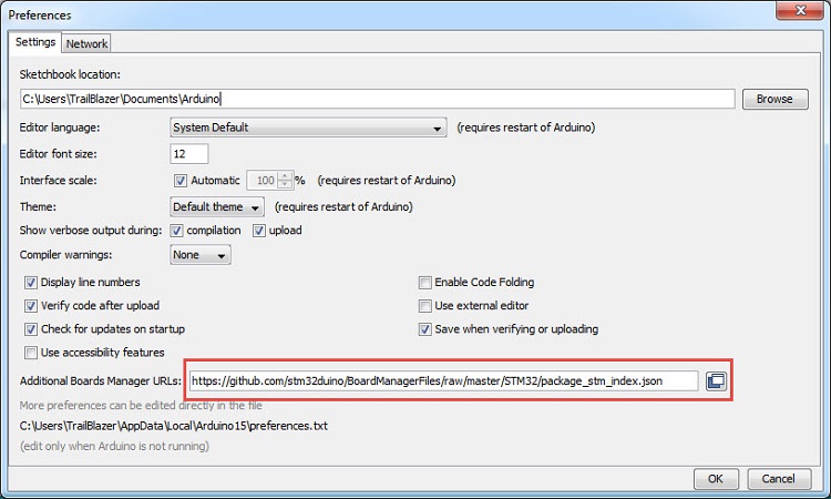
If you already have some URLs in this section, you can add more by separating them with comma. If you have worked with ESP8266 Boards, then you might be familiar with this process already. After adding the URL, click on OK.
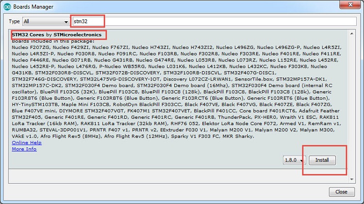
Now, go to Tools -> Board -> Board Manager… option and search for “stm32”. You will get a result like “STM32 Cores by STMicroelectronics”. Install the latest version. At the time of preparing this tutorial, the latest version is 1.8.0.
This will take some time as it will download and install some of the necessary files and tools. (I said some because, you have to download another tool from STMicroelectronics for this to work).
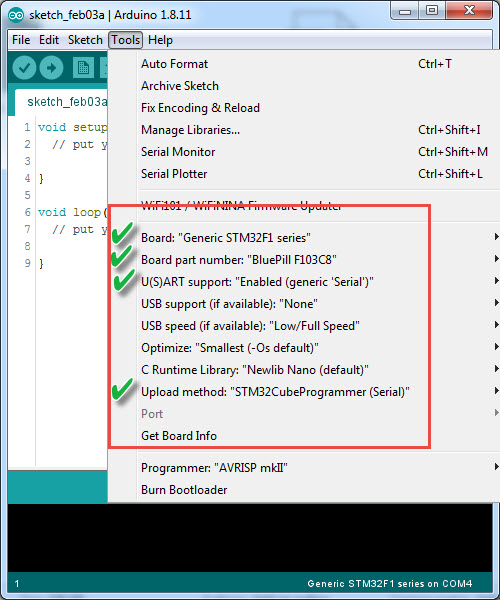
Now you can select the board from Tools -> Board -> Generic STM32F1 series. Once you select this board, a bunch of options will appear below for customizing your board type. The first important option is “Board part number”. Make sure that “BluePill F103C8” is selected.
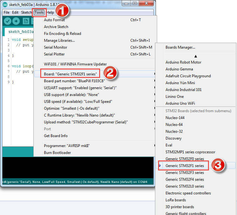
The other important options are “U(S)ART support”, make it as “Enabled (generic ‘Serial’)” and “Upload method”, make its as “STM32CubeProgrammer (Serial)”. You can leave the remaining options as their default values.
Downloading STM32CubeProgrammer
In the above step, we have selected “STM32CubeProgrammer (Serial)” as the upload method but the problem is this tool is not downloaded and installed by the Boards Manager. So, we have to manually install it. For that, go to the official STM32CubeProgrammer download page provided by STMicroelectronics using the link.
Click on Get Software option and it will take you Login/Register page. I suggest you to register with STMicroelectronics with a valid e-mail ID. Once you register, you can login and download the software. Extract the zip file and you will get a Windows exe file with name “SetupSTM32CubeProgrammer-2.3.0”. Double click and proceed with installation.
Make sure that the installation directory is default and don’t change anything. It might ask your permission to install some drivers for ST-Link. You can grant necessary permissions.
This completes the software setup for Arduino IDE to program STM32 Blue Pill. Let us proceed with writing a small program for blinking an LED and uploading it to our STM32F103C8T6 Blue Pill Board.
Blinky Program for STM32F103C8T6 Blue Pill Board
Make sure that you made the necessary changes to the Arduino IDE as mentioned in the previous section (selecting the correct board, etc.). Once that is done, make the connection between FTDI Programmer (i.e. USB to Serial Converter) and STM32 Board as mentioned before.
Now, before connecting the FTDI to the PC, make sure that STM32 Blue Pill Board is in “Programming Mode” i.e. connect the BOOT0 pin to HIGH. After that, connect the FTDI to the PC or Laptop. A COM port will be assigned to the programmer and select the same COM port in the Arduino IDE.
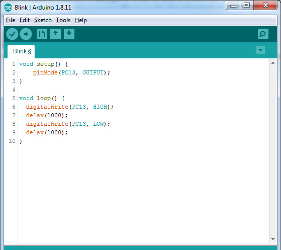
Write the Blinky program as follows. It is similar to the Arduino Blinky sketch but instead if LED_BUILTIN, I have used PC13 as the LED is connected to that pin of the MCU.
Code
void setup() {
    pinMode(PC13, OUTPUT);
}
void loop() {
  digitalWrite(PC13, HIGH);
  delay(1000);
  digitalWrite(PC13, LOW);
  delay(1000);
}
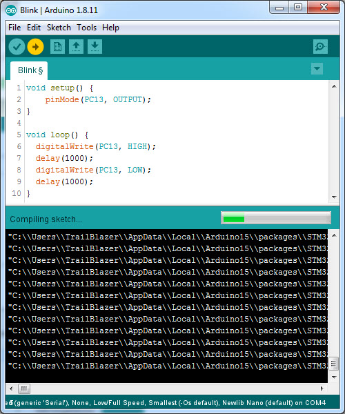
After this, you can click on Upload and the IDE will start compiling the code. It will take some time for compiling.
Once the compilation is successful, it will automatically invoke the STM32CubeProgrammer tool. If everything goes well, the IDE will successfully program the STM32 Board.
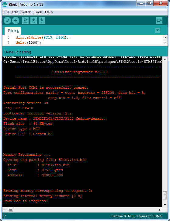
It will automatically reset the MCU and you can notice the LED blinking. Don’t forget to move the BOOT0 pins back to LOW position so that the next time you power-on the board, it will start running the previously uploaded program.
Package includes:
1×STM32F103C8T6 With 2 welded/unwelded pin headers