Description
The Digispark is an Attiny85 based microcontroller development board similar to the Arduino line, only cheaper, smaller, and a bit less powerful. With a whole host of shields to extend its functionality and the ability to use the familiar Arduino IDE the Digispark is a great way to jump into electronics, or perfect for when an Arduino is too big or too much.The Digispark is shipped fully assembled except for the two included and easy to solder headers.
features
Support for the Arduino IDE 1.0+ (OSX/Win/Linux)
Power via USB or External Source – 5v or 7-35v (12v or less recommended, automatic selection)
On-board 500ma 5V Regulator
Built-in USB
6 I/O Pins (2 are used for USB only if your program actively communicates over USB, otherwise you can use all 6 even if you are programming via USB)
8k Flash Memory (about 6k after bootloader)
I2C and SPI (vis USI)
PWM on 3 pins (more possible with Software PWM)
ADC on 4 pins
Power LED and Test/Status LED
Getting Started with ATtiny85
In this project, I will talk about ATtiny85, what are the tools required for Getting Started with ATtiny85 board, installing drivers for Windows OS and finally how to program ATtiny85 Microcontroller using Arduino IDE.
A Brief Note on ATtiny85
The ATtiny85 Microcontroller is possibly the smallest Microcontrollers available today. It is an 8-bit Microcontroller based on the AVR RISC Architecture. Physically, it needs only 8-pins for complete operation (although some packages like QFN16 use 16-pins just for packaging).
There are three variants of ATtiny85: ATtiny25, ATtiny45 and ATtiny85. The main difference between these three ICs is the amount of memory each device has (Flash, EEPROM and RAM).
ATtiny85 Microcontroller, the target device of this project has 8KB of In-system programmable Flash, 512B of EEPROM and 256B of SRAM.
ATtiny85 Board
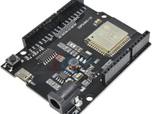
Several manufacturers started developing tiny development boards with ATtiny85 as the main controller. One such board is shown in the image below.
As you can see, apart from the ATtiny85 Microcontroller IC, there are a few other components on the board like a 5V Regulator, headers for I/O pins, few passive components and a MicroUSB port for programming and power supply.

Getting Started with ATtiny85 Board
Now that we have seen a little bit about ATtiny85 Microcontroller and its development board, lets dig into the aspects of how to use this board, what are the necessary tools (like Drivers) required and also how to program the ATtiny85 Microcontroller.
Let me start with programming ATtiny85. There are couple of ways you can program your ATtiny85 but I have chosen the easiest of all: using Arduino IDE to program ATtiny85. For this, you need to make some changes to the Arduino IDE.
Next important thing is the drivers. USB Drivers for ATtiny85 Board are very important as the driver is responsible for enabling the Arduino IDE to program the ATtiny85.
Setting up Arduino IDE
The first step is to setup Arduino IDE for programming ATtiny85. Open your Arduino IDE and go to File à Preferences. In the tab that says “Additional Boards Manager URLs:”, copy and paste the following link and click on ok.
http://digistump.com/package_digistump_index.json


Now, go to Tools → Board: → Board Manager… and search for “Digistump AVR Boards”. Select the same and click on install. If the installation is successful, you can see the board in Tools → Board: option. We will come back to this later.


Installing Drivers
Next step is to install the necessary USB drivers for the ATtiny85 board. I will specify how to install drivers for Windows system. Go to the following link and download the “Digistump.Drivers.zip” file. Extract the contents of the zip file and double click on “DPinst64” application to install the drivers.
NOTE: If your system is a 32-bit system, select “DPinst” application.
Once the drivers are successfully installed, you can plug in your ATtiny85 board to the computer using an USB cable. To check if the device is detected or not, go to Device Manager on your Windows and your device will be listed under “libusb-win32 devices” as “Digispark Bootloader”.
Programming ATtiny85 with Arduino IDE
Now, you are ready to upload your first program on to your ATtiny85 Microcontroller. You don’t have to plug in your device to the computer until the IDE says so. Even if you plug in, you have to disconnect and reconnect when asked.
First step in programming ATtiny85 is to select the board in Arduino IDE. Go to Tools → Board: and select “Digispark (Default -16.5mhz)” board.
There is a user LED connected to PB1 of ATtiny85. In order to blink that LED, use the following code.
void setup()
{
  pinMode(1,OUTPUT);
}
void loop()
{
  digitalWrite(1,HIGH);
  delay(1000);
  digitalWrite(1,LOW);
  delay(1000);
}
Click on upload button in Arduino IDE. Assuming you haven’t connected the ATtiny85 to the computer, the Arduino IDE will display a message saying “Plug in device now”. Connect your ATtiny85 board to the computer now and it will be programmed and the LED will start blinking.