")
Description
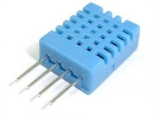
Used for testing the current environment temperature and humidity of the real-time change, the output analog voltage signal, can be connected to the microcontroller AD acquisition. Available in instrumentation, electrical
power equipment, air conditioning equipment, humidification and desiccant equipment, warehousing, meteorology and industrial automation and other fields.
Description
- Rated voltage: DC5V+- 5%
- Rated current: 5mA max (2mA AVG)
- Storage temperature and humidity range: -20~70℃ below 95%rh (without condensation)
- Humidity detection range: 0 ~ 3V output 0 ~100%rh
- Temperature detection range: 0 ~ 3V output -20℃ ~80℃
- Humidity accuracy :+- 5%rh
- Measurement accuracy: 0.5℃ power supply voltage 5V
- Linear voltage output
Application:
instrumentation, electrical power equipment, air conditioning equipment, humidification dehumidification equipment, warehousing, meteorological and industrial automation fields.
Getting started with the Temperature and Humidity Sensor Module LGHTM-01A Resistance Type Analog Voltage Output
In this tutorial you will learn how to use this sensor with Arduino uno. The room temperature & humidity will be printed to serial monitor
Hardware required
- Arduino UNO
- T&H Sensor analog voltage output
- Jumper wires
- Capacitor 47uf/10v
- resistor 10k,100k
Connecting the Hardware
Connect temperature and humidity sensor to the arduino board with the resistors and capacitor shown in the schematic.Follow the schematic diagram carefully. A 10K resistor is connected to T and Ground pin . Another 100K and 47uF/10v capacitor is connected to H and Ground pin.


Upload the sample sketch
const byte nsum=10;
int humidityPin=A0;
int TempPin=A1;
unsigned int sensorValue2 = 0; // variable to store the value coming from the sensor
unsigned int sensorValue3 = 0; // variable to store the value coming from the sensor
void setup() {
Serial.begin(9600);
}
void loop() {
for (byte i=0;i<nsum;i++)
{ // read 10 values for T & H
sensorValue2 += analogRead(A0);
sensorValue3 += analogRead(A1);
}
// average the value
int sensorValue2Avg=sensorValue2/nsum;
float RH= 0.1515*sensorValue2Avg-12.0;
int sensorValue3Avg=sensorValue3/nsum;
float Vt=(float) sensorValue3Avg*5.0/1023.0;
float R=(5.0-Vt)*10.0/Vt; // convert the value to relative humidity
float TinC=281.583*pow(1.0230,(1.0/R))*pow(R,-0.1227)-150.6614+5;
float TinF=TinC*(9.0/5.0)+32; // convert the temperature to fahrenheit
// print to serial monitor
Serial.print(RH,0);
Serial.println(” %RH”);
Serial.print(TinC,1);
Serial.println(” deg C”);
Serial.print(TinF,1);
Serial.println(” deg F”);
Serial.print(R);
sensorValue2=0;
sensorValue3=0;
delay(5000);
}
Testing the circuit
Upload the program to the arduino board and open the serial monitor. If it works correctly you should get the following result from the serial monitor.