Description
2. With a variety of single chip microcomputer interface
3. The RGB tricolor current-limiting resistance to prevent burn out
4. is obtained by PWM adjusting three primary colors can mix different colors
5. Working voltage: 5 v
2. PCB color: black
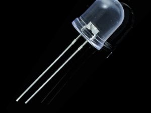
3. USES 5050 full-color super bright LED
4. To prevent burn resistor LED
5. Can meet all kinds of single chip microcomputer
6. High light LED
7. Working voltage: 3.3 V / 5 V
8. Weight: 4 g
9. Can be used directly plugged into the motherboard Arduino, without dupont lines to connect
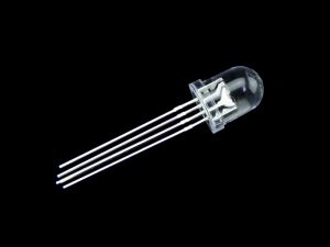
Getting started with the RGB module KY 016
Learn using RGB 3 Color LED Module KY-016 in Arduino. RGB LED module is capable of producing lights of different colors using a single LED. We can generate light of any color code through this module. In this, we will generate lights of all colors. We are using Arduino Uno and RGB 3 Color LED Module KY-016 for this. So, let’s start.
Hardware required
- RGB module KY 016
- Arduino Uno
- Jumper wires
Connecting the Hardware
Make the circuit as per the given diagram. Connect red LED pin to pin 7 of Arduino. Then, connect the green LED pin to pin 9 of Arduino. Now, connect the blue LED pin to 8 of Arduino. Connect (-) pin of the module to the GND pin of Arduino. The RGB LED module will not require any limiting resistors.
| KY-016 | Arduino |
| R | Pin 11 |
| B | Pin 10 |
| G | Pin 9 |
| – | GND |

Upload the sample sketch
This is code for the RGB LED module in Arduino. Firstly, we declare pins for red, green and blue pins. Then, set the declared pins in output mode. We use the ‘for’ loop to generate light of all the color codes. The first loop generates color in decreasing order, whereas the second loop generates color in increasing order. You can use the serial monitor to determine the light of which color code is generated.
int red = 7; // select the pin for the red LED
int blue = 8; // select the pin for the blue LED
int green = 9 ;// select the pin for the green LED
int val;
void setup ()
{
pinMode (red, OUTPUT);
pinMode (blue, OUTPUT);
pinMode (green, OUTPUT);
Serial.begin (9600);
}
void loop ()
{
for (val = 255; val> 0; val –)
{
analogWrite (7, val);
analogWrite (8, 255-val);
analogWrite (9, 128-val);
delay (10);
Serial.println (val, DEC);
}
for (val = 0; val <255; val ++)
{
analogWrite (7, val);
analogWrite (8, 255-val);
analogWrite (9, 128-val);
delay (10);
Serial.println (val, DEC);
}
}
Results
Upload the above-given code to the Arduino Uno Board after the components are set as per the Circuit Diagram. Now you can see RGB lights of different colors generating subsequently.