Description
The RFM69W is a transceiver module capable of operation over a wide frequency range, including the 868 MHz license-free ISM (Industry Scientific and Medical) frequency band.Its highly integrated architecture allows for a minimum of external components whilst maintaining maximum design flexibility. All major RF communication parameters are programmable and most of them can be dynamically set. The RFM69W offers the unique advantage of programmable narrow-band and wide- band communication modes.The RFM69W is optimized for low power consumption while offering high RF output power and channelized operation.
Features:
- +20 dBm for RFM69W Power Output Capability
- High Sensitivity: down to -120 dBm at 1.2 kbps
- High Selectivity: 16-tap FIR Channel Filter
- Bullet-proof front end: IIP3 = -18 dBm, IIP2 = +35 dBm,80 dB Blocking Immunity, no Image Frequency response
- Low current: Rx = 16 mA, 100nA register retention
- Programmable Pout: -18 to +20 dBm in 1dB steps
- Constant RF performance over voltage range of chip
- FSK Bit rates up to 300 kb/s
- Fully integrated synthesizer with a resolution of 61 Hz
- FSK, GFSK, MSK, GMSK and OOK modulations
- Built-in Bit Synchronizer performing Clock Recovery
- Incoming Sync Word Recognition
- 115 dB+ Dynamic Range RSSI
- Automatic RF Sense with ultra-fast AFC
- Packet engine with CRC-16, AES-128, 66-byte FIFO
- Built-in temperature sensor
Applications:
- Automated Meter eading
- Wireless Sensor Networks
- Homeand Building Automation
- Wireless Alarm and Security Systems
- Industrial Monitoring and Control
- Wireless M-BUS
How to get started with RFM69W 868Mhz wireless transceiver
The RFM69HCW is an inexpensive and versatile radio module. You can use it to send text or binary data between two or hundreds of modules. It’s perfect for building inexpensive short-range wireless networks for home automation, citizen science, and more.
This RFM69W is 868Mhz module
Hardware Overview
Frequency
The RFM69W transmits the ISM (Industry Scientific and Medical) band, a st of frequencies set aside for low-power, short-range, license-free radios.
Faranux sells RFM69W 868 MHz version. These frequencies are legal in different areas. The actual regulations are a bit of a patchwork, so check your local regulations for other areas.
Range
How far will the signal reach? Outside with few obstruction, you should be able to get a solid link for hundreds of meters. Indoors we’ve seen it work for 50 meters through multiple walls.
The RFM69W is capable of transmitting at up to 100mW and up to 300 kb/s, but you can change both of those values to fit your application. For example, you can maximize range by increasing the transmit power and reducing the data rate. Or you can reduce both for short range wireless sensor networks that sip battery power.
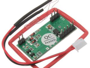
Board Pinout
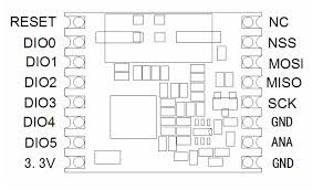
The RFM69W breakout board gives you access to all pins on the RFM69W, but in the majority of cases you will only need seven of them, Here’s an overview of the pins we’ll be using:
Power
| Boar label | Name | Function |
| 3.3V | Power | 3.3V power supply (at least 130 mA) |
| GND | Ground | Power Ground |
Data
| Board label | Name | Function |
| MISO | Master In Slave Out | Data from RFM69W to micro-controller |
| MOSI | Master Out Slave In | Data from micro-controller to RFM69W |
| SCK | Serial Clock | Clock signal from micro-controller to RFM69W |
| NSS | Slave Select | Select signal from micro-controller to RFM69W |
| DIO0 | Digital I/O 0 RX interrupt | Received data ready interrupt signal from RFM68W to micro-controller |
Antenna
| Board label | Name | Fucntion |
| ANA | Antenna | Wire antenna |
| GND | Ground | Antenna ground( same as power ground)(you can either G pin adjacent to the antenna pin) |
The unused pins labeled 1 to 5 have functions we won’t be using. See the RFM69W datasheet for more information.
Power requirements
The RFM69W will run on voltages from 1.8 to 3.6V, and can draw up to 130 mA of current when it’s transmitting.
Important! Do not power your RFM69W with 5V or connect the data lines directly to a 5V microprocessor. Doing so will damage the device.
The easiest way to use this board is to connect it via logic level translator to a 5V Arduino. See the diagram in the hardware connection section.
In this tutorial we’ll use a 5V Arduino powered by a PC and a bidirectional logic level converter.
Interface and Example Code
The RFM69W can’t do anything by itself; it needs to be connected to a microcontroller such as an Arduino. The RFM69W uses a four-wire Synchronous Peripheral Interface (SPI) plus an interrupt line. Most microcontrollers, including the Arduino, offer an SPI interface.
Felix Rusu of LowPowerLab has written an excellent Arduino library for the RFM69 that handles the details of setting up the module and sending and receiving data. This guide will cover interfacing the RFM69W to an Arduino microcontroller using this library.
In this tutorial we’ll show you how to get two modules talking to each other, but keep in mind that you can use more than two modules in your projects.
Here’s what you’ll need:
2 x RFM69W modules (with matching frequencies): Here we user the one with 868 Mhz
You will need two Arduinos. You can use the RFM69W with any Arduino, but remember that the RFM69W is a 3.3V board that means the RFM69W pins works with 3.3V to send it data unlike Arduino UNO which use 5V, thus we will need a level shifter to use our Arduino UNO.
2 x Arduino UNO R3
2 x Bidirectional Logic Level Converter
We will connect these to the Arduino using headers and jumper wires:
2 X Break away headers – straight
2 x Jumper Wires M/F, pack of 10
You will need some wire to make antennas, and a couple of LEDs that we will make blink when data is sent or received:
2 x general purpose LEDs
About one foot of general purpose wire, or you can use a jumper wire as I did.
You will also nee soldering tools and solder.
Hardware connections
Connecting the RFM69W to an Arduino
There are a lots of ways to connect together. In this tutorial, we’re going to solder male breakaway header to RFM69W board, and use M/F jumper wires to connect everything together. Of course, you can use whatever wiring methods you wish.
Step 1: Solder male header onto RFM69W:
Break off one 8 pin length of male breakaway header, and solder it to the “NSS, MOSI, MISO, SCK, GND” side of the RFM69W board. You can solder it to the top or bottom, your choice.
Note: The board is laid out so that all the interface connections you need are on one side of the board, so you should only solder headers or wires to “NSS, MOSI, MISO, SCK, GND” side of the board. Leave the opposite side empty for your antenna.
Repeat for the second RFM69W.
Step 2: Solder female headers onto the Bidirectional Logic level converter
Solder the four Male headers to the level shifter. Repeat for the second logic level shifter.
Step 3: Use jumper wires to connect the RFM69W to Arduino UNO
You can connect the RFM69W to a 5V Arduino, if you use a Logic Level transistor between them. The translator translates the Arduino’s 5V signals to 3.3V signals, which won’t damage the RFM69W: The momentary button should be bridging pin 3 and ground, the LED should be attached to pin 9, and the data pins NSS, MOSI, MISO, and SCK should connect to pins 10, 11, 12, 13 in that order.
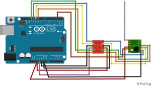
5V Arduinos have both a 5V and 3.3V supply . Here we’re using the 5V supply (purple wire) to power the high-voltage side of the logic level translator, and the 3.3V supply (red wire) to power both the RFM69W and the low-voltage side of the logic level translator. Remember to never connect 5V to the RFM69W pin.
External Status LED
When you press the button on the SENDER RFM69W, it will send a short message to the RECEIVER RFM69W and wait for an ACK (acknowledgement that message was received) from the RECEIVER RFM69W. If the ACK was received, the SENDER will blink the onboard LED a few times. The RECEIVER listens to a specific token, and it alternates the onboard LED state from HIGH to LOW or vice versa whenever this token is received.
One more thing: the example code we’ll get to in few pages work like this:
When you press the button on the SENDER RFM69W, it will send a short message to the RECEIVER RFM69W and wait for an ACK (acknowledgement that message was received) from the RECEIVER RFM69W. If the ACK was received, the SENDER will blink the onboard LED a few times. The RECEIVER listens to a specific token, and it alternates the onboard LED state from HIGH to LOW or vice versa whenever this token is received.
Unfortunately, we can’t use the Arduino’s built-in LED for this, because that port (D13) is also used by the SPI port’s SCK line. We use the SPI port to communicate with RFM69W, so this LED will be on a lot the time.
To make up for this, the example code written so you can stick any old LED into your Arduino, with the long positive lead in D9, and the short (negative) lead in GND.
The Antenna
Important: You MUST attach an antenna to the board. Aside from not working without an antenna, transmitter can be damaged if they transmit without an antenna present.
Creating an antenna is not as hard as it may sound. The simplest antenna is a wire cut to a proper length and soldered to the”ANA” pin. The length depends on the frequency of your board is marked on the bottom of the board for your convenience.
Antenna placement For antenna placement you have a few options:
Single antenna: The simplest option is to solder a properly-sized antenna wire to the “ANA” header hole (the one with the circle around it), and stick it straight up. That’s it!
Running the example code
Felix Rusu of LowPowerLab has written an excellent Arduino library for the RFM69 that handles the details of setting up the module and sending and receiving data. This guide will cover interfacing the RFM69 to an Arduino micro-controller using this library.
Installing the RFM69 library
Hopefully you’ve done a bit of Arduino programming an know how to install a library. Download the RFM69 library from lowPowerLab’s gitHub page and do the basic process
Note: this library is not found in the Arduino library manager currently, so you’ll have to download the library and add it using the Add .ZIP library.. option ound under sketch; Include Library menu.
The basic process is:
- Download a copy of this repository
- Open the above archive, go into the ”Libraries/Arduino” Folder, copy the “RFM69” folder, ad add the folder via the library Manager or paste it into your “Arduino/libraries” folder.
- Restart your Arduino IDE.
Easy!
Plug in the hardware
In this tutorial we’re going to set up two Arduino/RFM69 nodes and get them to communicate with each other. At this point, you should have two matching Arduino plus RFM69W nodes. We’ll need to figure out the serial ports associated with these nodes. Plug one USB cable into your computer. A new COM port number should be added to Arduino IDE’s “Tools/Port” list. Write it down. Now plug in the other USB cable from the second node. Another COM port number should appear. Write that one down as well.
Node1: SENDER
On this circuit you must add a pushbutton connected on D3 witha 1Kohm pull-up resistor as on the scheme below:
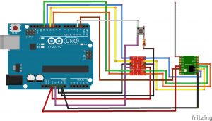
Now upload the sketch to your first node (SENDER). Remember that you should set the “Tools/Port” menu to the COM port you wrote down earlier for the FIRST node.
Node 2: RECEIVER
On this receiver node’s Arduino, you should add an LED on the D9 pin of the Arduino as shown below.
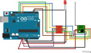
Upload the sketch to your SECOND node. Change the “Tools/Port” menu to the second COM Port you wrote down from above, and upload. That’s it, we’re done!
The code is commented to describe its operation, but here is a basic breakdown of what is going on:
1. Include the libraries
These are the libraries linked to earlier, in addition to the standard SPI.h library for serial communication.
2. Define the constants
Tell the chip who it is, what network it is on, what its encryption code is, whether it is the sender or receiver, which of a possible set of receivers/senders the unit is, etc.
3. Initialize the radio
This is the housekeeping step where all those parameters we just defined get applied, in addition to setting up the serial monitor for debugging purposes.
4. Go to sleep and wait for an interrupt
Using an interrupt on the button and putting the unit into sleep helps to save power while the unit is idling. Interrupts are a highly efficient tool to wake a device upon an event, and allow a device to do other things in the meantime before and after the interrupt takes place.
5. Transmit upon an interrupt flag
This will send a message to the receiver after the sender’s button is pushed. In this case the message is “All About Circuits.”
6. Receive
The receiver checks and confirms that it has received a message. It then prints the message to serial, and also prints the RSSI (Received Signal Strength Indicator) to let you know how strong the signal was in dBm. The receiver then toggles the LED to let the user know a message was received.
7. Acknowledge
Send an ACK bit back to the sender to let it know that the message was received.
8. Sleep
Put the device back into a low power sleep mode to conserve battery and wait for another interrupt.
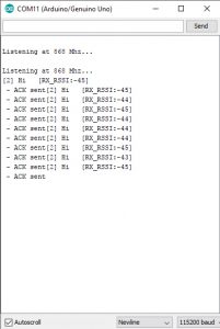
If you hook up your receiving unit to your computer to use the serial monitor terminal you should see this after pressing the button a few times:
Running the Sketches
You now have two nodes that will send messages to each other, and the sender will control the LED on the receiver node using the pushbutton on it. Open the serial monitor with COM set to the receiver node, and also set to 115200 baud rate and try to push the button. Your screen should look like this:
The applications of these modules are tremendous for hobbyists and engineers alike: a simple, cheap, powerful digital transceiver that can be interfaced to almost anything.
Arduino Sketch:
Arduino libraries
RFM69 library by lowPoweLab
Document: