Description
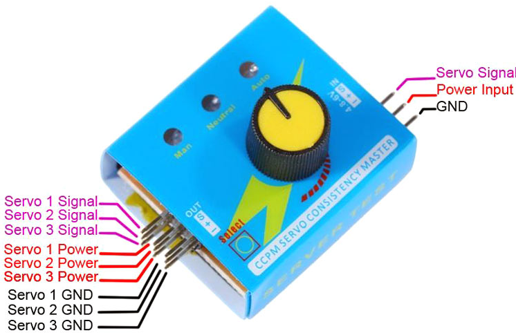
The Digital Multi Servo Tester ESC RC Consistency CCPM Master Speed Control offers 3 modes to check servos or ESC. The Manual Mode allows you to turn the knob to different speeds and check the reaction time. The Neutral mode makes the servo go back to the neutral point. The Automatic “Window Wiper’’ Mode makes the servo swing like a window wiper in the largest angle possible. This servo tester can connect to up to 3 servos simultaneously. You can also connect up to 3 ESCs to test and compare their reaction time respectively. It can be operated on Voltage Range 4.8V to 6V with indicator LEDs to indicate the current state in the test. It is very handy tool to have when you deal with lot of robotic projects and electronic projects in general and want to ensure the motors are working just fine.
Package includes:
1×Multi Servo Tester
Features
- Adjustment: manual, automatic, and the median.
- Indicator LEDs
- Can test up to 3 ESC simultaneously
Specifications
- Output: ≤ 15mA (5.0)
- Input: DC 4.2-6.0Vdc
- Output Signal: 1.5ms ± 0.5ms
- Type: CCPM Servo Tester, ESC or Servo tester
Getting started with the Servo Tester
The Servo Tester works with 4.8V-6.0V input voltage and could control up to three servo motors. However, the control mode of the servo can be selected using a selection button. The servo tester has three modes of operations, Automatic, Manual, and Neutral or Center mode.
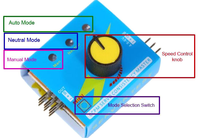
In automatic mode, the servos operate in such a way that the servo motors swing like window wipers in the biggest angle.
In Manual mode, the servos react as per the rotation of the speed knob. It is useful to check the reaction time of the servo motors.
In Neutral or Center mode, the servos are centered in a neutral position for servo setup in a model.
It has an LED indicator that is useful for the user to determine what mode is currently running in the servo tester.
Servo Tester Pins Configuration
|
Pin Name |
Description |
|
OUT – S |
The three-pin column in 3×3 berg is used for three Servo signal out |
|
OUT – + |
The middle three-pin column in 3×3 berg is used for three Servo signal Power line |
|
OUT – – |
The three-pin column in 3×3 berg is used for three Servo signal GND |
|
IN – S |
Servo Signal Input |
|
IN – + |
Servo Power Input |
|
IN – – |
Servo GND Input |
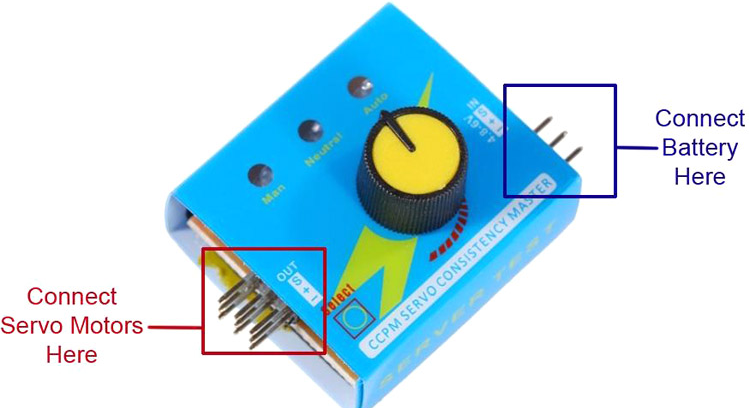
Connecting Servo Tester to servo motor
The connection to servo motor should be done properly to avoid any untrue results from the test.
Now we observe how each pin should be connected respectively,