Description
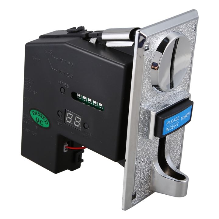
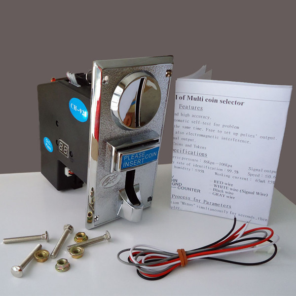
This is a multi coin Acceptor (MCA), It accepts up to 3 kinds of different coins at the same time. This type of coin selector is widely used in Vending machine, Arcade Game, Message chair, and other self–management system.The multi coin acceptor is mainly based on material, weight and size to identify coins. . The multi coin acceptor is very stable and accurate even when environment changes such as temperature, and humidity etc… In order to increase the accuracy, we suggest different version of coins use different channel to set up.
Features:
a. Capable of accepting all worldwide Coins and Tokens.
b. Intelligent CPU software control, and high accuracy .
c. Self-programming without PC.
d. Accept 1~3 different kinds of coins at the same time.
e. Free to set up pulses’ output.
f. Prevent not only electric shock but also electromagnetic interference.
g. Automatic self-test for problems.
Specifications:
- Coin diameter: 15mm~32mm
- Atmospheric pressure: 86Kpa-106Kpa
- Coin thickness: 1.2mm~3.4mm
- Working humidity: ≤95%
- Working voltage: DC +12V ±10%
- Speed: ≤0.6s
- Working current: 65mA ± 5% A
- accuracy rate of identification:99.5%
- Signal output:pulse
Note: This Multi Coin Acceptor comes with a printed copy of setting instructions and calibration process
Getting started with the Multi Coin Acceptor (3 coins types)
Purpose of this project is to write a code to control coin acceptor with Arduino so it can be used in other projects
Hardware required
- Arduino UNO
- Jumper wires
- Multi Coin Acceptor (3 coins types)
Now, The Setup:
First the switches…
select “NC” by sliding the top switch to the bottom position.
select “FAST” by sliding the bottom switch to the top position.
Power Up the unit with a 12v supply.
The Setting Process for Parameters:
1. Hold on button “ADD” and “MINUS” simultaneously for seconds. Letter “A” shows up from the display.
2. Hold on button “SET” for seconds. Letter “E” shows up.
Use button “ADD” and “MINUS” to adjust number for TYPES of coins.
Next, hold on the button “SET” for seconds.
3. “H1” shows up. Use button “ADD” and “MINUS” to adjust number as 15-30 for sampling for type 1.
Next, hold on the button “SET” for seconds.
4. “P1” shows up. Use button “ADD” and “MINUS” to adjust number for output’s signals/pulses for type 1.
Next, hold on the button “SET” for seconds. The maximum pulse is 50.
5. “F1” shows up. Use button “ADD” and “MINUS” to adjust accuracy. Next, hold on the button “SET” for seconds. The value is from 1 to 30, and 1 is the most accurate. Normally, 7-10 will be fine.
6. The first kind of coin has been programmed so far.
7. Please repeat No.3- No.5 until Letter “A” shows up again. Hold on button “SET” for seconds.
8. Letter “E” shows up again. Please power off and on. Parameter is saved.
Tip: Free to hold on button “SET” for seconds for skipping if revising parameter on code is not needed.
Sampling
1. Hold on button “SET” for seconds, and “A1” shows up from display.
2. Please insert coins of TYPE 1 into coin entry until “A1” shows up again.
3. Please repeat No.1 and No.2 until all types of coins has been sampled.
4. The system will restart automatically after finished.
Tip: Free to power off if these is no more types of coin for sampling.
AP Mode
Free to control output pulse ratios by using
Free to adjust 1-50 pluses to output 1 signal based on “P”. EX: 3 pluses output 1 signal.
1. Please hold on button “SET” and “ADD” simultaneously for seconds, then hold on the button “SET” for seconds.
2. “AP” shows up. Please use button “ADD” and “MINUS” to adjust number.
3. The default value of AP mode is 1.
Connecting the Hardware

the sample sketch
Now, Fire up the Arduino IDE and let start coding:
PROGRAM START:
const int coinInt = 0;
//Attach coinInt to Interrupt Pin 0 (Digital Pin 2). Pin 3 = Interrpt Pin 1.
volatile float coinsValue = 0.00;
//Set the coinsValue to a Volatile float
//Volatile as this variable changes any time the Interrupt is triggered
int coinsChange = 0;
//A Coin has been inserted flag
void setup()
{
Serial.begin(9600);
//Start Serial Communication
attachInterrupt(coinInt, coinInserted, RISING);
//If coinInt goes HIGH (a Pulse), call the coinInserted function
//An attachInterrupt will always trigger, even if your using delays
}
void coinInserted()
//The function that is called every time it recieves a pulse
{
coinsValue = coinsValue + 100;
//As we set the Pulse to represent 5p or 5c we add this to the coinsValue
coinsChange = 1;
//Flag that there has been a coin inserted
}
void loop()
{
if(coinsChange == 1)
//Check if a coin has been Inserted
{
coinsChange = 0;
//unflag that a coin has been inserted
Serial.print(“Credit: rwf”);
Serial.println(coinsValue);
//Print the Value of coins inserted
}
}
Testing the circuit
open your serial monitor by clicking on the icon in the right top corner(like search icon) .This simple program will write the total value of coins inserted to the serial monitor.


