Description
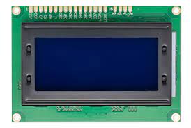
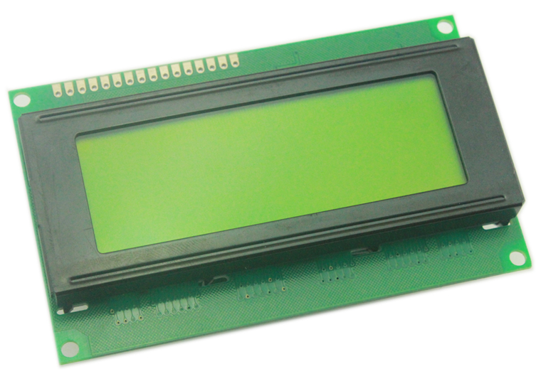
When you are designing complex hardware interfaces—like a diagnostic dashboard for an electric motorcycle battery management system—you need to display voltage, temperature, current, and fault codes all at the same time. The 20×4 Character LCD Screen provides the exact real estate you need, comfortably displaying up to 80 characters simultaneously.
Whether you are building advanced industrial IoT hubs, or structuring the syllabus for the Electronics Bootcamp, mastering this classic display is a right of passage for every embedded systems developer.
The Raw Parallel Experience
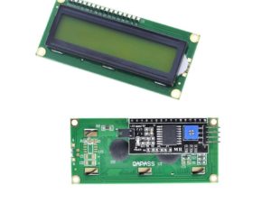
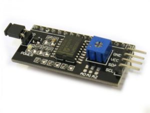
This specific 2004 module features a raw 16-pin header and does not include a pre-soldered I2C backpack. While I2C saves pins, wiring the display directly via parallel communication (typically using 6 digital pins in 4-bit mode on an Arduino) offers distinct advantages:
- Speed: Parallel data transfer is significantly faster than standard I2C, eliminating screen flickering when updating multiple sensor values rapidly.
- Address Conflicts: It frees up your I2C bus for other crucial sensors (like an MPU6050 or DS1307 RTC) without worrying about address collisions.
- Fundamental Learning: It is the absolute best way to learn how the ubiquitous HD44780 display controller actually processes data and command registers.
Contrast and Backlight Control
To get the crisp, dark text against the classic yellow-green backlight shown in the product image, you must wire a 10kΩ potentiometer to Pin 3 (V0). This allows you to manually adjust the liquid crystal contrast depending on the ambient lighting of your workshop. Furthermore, you can connect the backlight anode (Pin 15) to a PWM-capable pin on your microcontroller to dynamically dim the screen brightness via code.
Key Features:
- Massive Display Area: Four lines of text provide enough room to build nested menus and full user interfaces without constant scrolling.
- Broad Library Support: Works instantly with the standard
LiquidCrystal.hlibrary included natively in the Arduino IDE. - High Contrast: The classic yellow-green background ensures excellent readability even in direct sunlight.
Technical Specifications:
- Display Capacity: 20 Columns x 4 Rows
- Operating Voltage (VDD): 5V DC
- Driver IC: HD44780 (or highly compatible equivalent)
- Backlight: LED (Yellow-Green)
- Interface: 4-bit or 8-bit Parallel
- Module Dimensions: ~98mm x 60mm x 14mm
- Viewing Area: ~76mm x 26mm
How to get started using LCD 20×4 display
This Arduino LCD tutorial will show you to interface a character LCD with an Arduino. You can use the information from this post to build your own LCD based Arduino projects.
Required materials:
- LCD 20×4
- Arduino Uno
- Jumper wires
- Breadboard
- 1k Potentiometer
Hardware Assembly
The first step is to solder the 16 pin male headers onto the LCD. You can then use either a 16 pin female header to connect to the Arduino or just use a female to female connector. If you are for interfacing an Arduino for the first time, it’s easiest to use a breadboard.

The first thing you need to do before working on the LCD is to check it. For this, do the connections as shown in the diagram above. Connect pin 15 on the LCD to Arduino’s 5V pin. Next, connect pin 16 on the LCD to the Arduino’s GND pin. These pins are used to power the LCD’s backlight.
Next, you need to set up the logic for the LCD. To do this, connect pin 1 on the LCD to the Arduino’s GND pin. Then, connect pin 2 on the LCD to the Arduino’s 5V pin. Next, you need to set up the contrast adjusting potentiometer. Take the 10K potentiometer and connect the first terminal to the Arduino’s 5V pin and the second terminal (middle pin) to the LCD’s pin 3(Vo) and the third terminal to the Arduino’s GND pin.
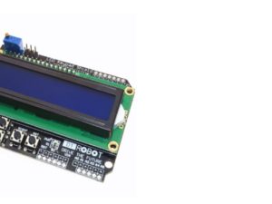
Next, power up the Arduino. You will notice that the backlight on the LCD turns ON. Also, when you turn the knob on the potentiometer, the character blocks on the LCD turn bright/dim. Check out the picture on below to see what I’m talking about. If your LCD displayed what is shown in the photo below, it means that your LCD is correctly set up! If you were not able to achieve this, double check your connections and your potentiometer.

Completing the Connections
Now, we need to connect the data lines and other pins that work with the LCD. Check out the connection diagram below.

Let’s start with connecting the control wires for the LCD. Connect the LCD’s pin 5 (RW) to the Arduino’s GND pin. This pin is not used, and serves as the Read/Write pin. Next, connect the LCD’s pin 4 (RS) to the Arduino’s digital pin 7. The RS pin is used to tell the LCD whether we are sending it data or commands (to change the position of the cursor). Next, connect the LCD’s pin 6 (EN) to the Arduino’s digital pin 8. EN is the enable pin on the LCD, this is used to tell the LCD that data is ready for reading.
Next, we have to connect the four data pins on the LCD. Connect the LCD’s pin 14 (DB7) to the Arduino’s digital pin 12. Then, connect the LCD’s pin 13 (DB6) to the Arduino’s digital pin 11. Next, the LCD’s pin 12 (DB5) to the Arduino’s digital pin 10, then the LCD’s pin no 11 (DB4) to the Arduino’s digital pin 9.
Make sure the connection in the program is the same as your connections:
Uploading the Code to the Arduino LCD
We can now try displaying something on the LCD through the Arduino. Before you do that, you need to download the Arduino LiquidCrystal library. Next, you need to extract the “LiquidCrystal” folder from the download file. Then, copy and paste the “LiquidCrystal” folder inside the Arduino’s directory,
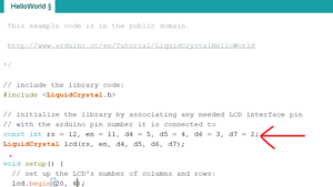
Next, open up your Arduino IDE and then go to: File–>Examples–>LiquidCrystal–>HelloWorld.

Before to Upload the code to your Arduino please edit the lcd.begin(16,2) to lcd.begin(20,4). as shown below

Then Upload the code to your Arduino. You will see the following display on your LCD.

Working With the Arduino LCD
Try tinkering with the code for the LCD. Basically, there are three main functions used for controlling the text on the LCD:
- lcd.begin(total columns, total rows)
-This function is used inside the setup() to initialize the size of the LCD we are using. If it is 20×4, then: lcd.begin(20,4), else if it is 16×2, then: lcd.begin(16,2). - lcd.setCursor(column number, row number)
– This function places the cursor of the LCD on the desired position. Any text displayed after this function will start from the position you have mentioned. For example, use: lcd.setCursor(4,0), i.e., fifth column and first row (since it starts from 0,0). - lcd.print(“text”)
-This function is used to print the text on the LCD. Whatever string is placed inside the ” “, gets displayed on the LCD.
Package includes:
1× Green/blue LCD 20*4 Display