Description
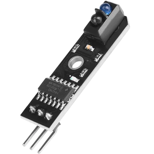
When infrared light fall on a white surface it is almost full reflected and in case of black surface light is completely absorbed. The sensor use an IR Transmitter and an IR receiver also called photo diodes. They are used for sending and receiving light.
When infrared rays falls on white surface, it’s reflected back and catched by photodiodes which generates some voltage changes. When IR light falls on a black surface, light is absorb by the black surface and no rays are reflected back, thus photo diode does not receive any light or rays.
Based on the above principle you can use the line follower sensor to sense white surface then arduino gets 1 as input and when senses black line arduino gets 0 as input.
Features:
Power supply: +5V
Operating current: <10mA
Operating temperature range: 0°C ~ + 50°C
Output interface: 3-wire interface (1 – signal, 2 – power, 3 – power supply negative)
Output Level: TTL level (black line of low effective, high efficient white line)
Getting started with the IR Line Tracking Sensor
In this experiment, we will use an IR Line tracking sensor module and the on-board LED to build a simple circuit to make a tracking line. Since the LED has been attached to pin 13, connect the pin OUT to digital pin 2 of the Arduino Uno board. When the tracking sensor detects reflection signals (white), the LED will be on. Otherwise, it will be off (black line).
Hardware required
- Arduino UNO
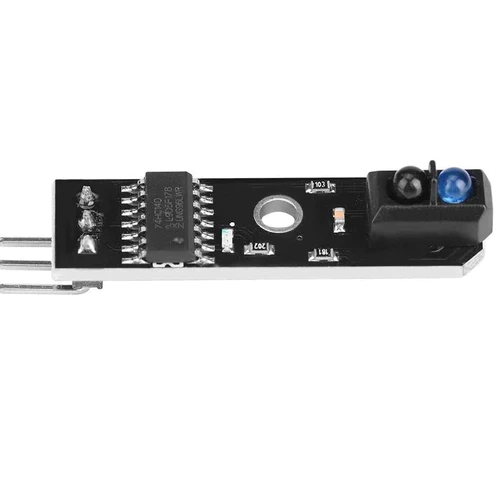
- IR Line Tracking sensor
- Jumper wires
Connecting the Hardware
Build the circuit as below digram:
| Arduino UNO | IR Line Tracking Sensor |
| +5V | VCC |
| GND | GND |
| D2 | OUT |

Code Program
After above operations are completed, connect the Arduino board to your computer using the USB cable. The green power LED (labelled PWR) should go on.Open the Arduino IDE and choose corresponding board type and port type for you project. Then load up the following sketch onto your Arduino.
const int trackingPin = 2; //the tracking module attach to pin 2
const int ledPin = 13; //pin13 built-in led
void setup()
{
  Serial.begin(9600);
  pinMode(trackingPin, INPUT); // set trackingPin as INPUT
  pinMode(ledPin, OUTPUT); //set ledPin as OUTPUT
}
void loop()
{
  boolean val = digitalRead(trackingPin); // read the value of tracking module
  if(val == HIGH) //if it is HiGH
  {
    digitalWrite(ledPin, LOW); //turn off the led
    Serial.println("Detect: Black!");
  }
  else
  {
    digitalWrite(ledPin, HIGH); //turn on the led
    Serial.println("Detect: White!");
  }
}
RUNNING RESULT
A few seconds after the upload finishes, set it down on a piece of paper with a dark line (at least ½” wide). You may use a Sharpie Marker, electrical tape, or dark paint. When the module gets on a black line, it output high and the corresponding LED stays off, the Serial Monitor output: “Detect: Black!”;

when it meets a white area, it outputs low and the LED lights up, the Serial Monitor output: “Detect: White!”.


