Description
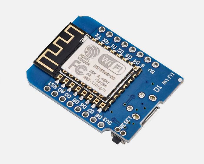
It is a mini WIFI board based on ESP-8266EX. 11 digital input/output pins, all pins have interrupt/PWM/I2C/one-wire supported(except D0) .
The development board features WiFi-SoC ESP8266 and is made for fast Internet-of-Things (IoT) prototyping. It is flashed with the latest firmware version and can be set up and programmed right away with the onboard micro USB connection. With only a few lines of code, the NodeMCU Dev Kit connects to your local network and ready for control by other network members like computers and smartphones.The d1 mini is an ESP8266 development board that is compact, versatile and very easy to use with the Arduino IDE.
How to get started in Arduino
On Linux & MAC OSX, you don’t need install it, comes preinstalled with OS.
1. Install Arduino 1.6.7 from the Arduino website.
2. Start Arduino and open Preferences window.
3.Enter http://arduino.esp8266.com/stable/package_esp8266com_index.json into Additional Boards Manager URLs field. You can add multiple URLs, separating them with commas.
4. Open Tools→Board:xxx→Boards Manager and install esp8266 by ESP8266 Community (and don’t forget to select your ESP8266 board from Tools > Board menu
after installation).
Installing with GIT (Recommend):
We recommend using GIT to install Hardware package,
Getting started with the ESP8266 ESP-12 NodeMCU WeMos D1 Mini WIFI 4M Bytes Development Board Module
This tutorial is a step-by-step guide that shows how to build a standalone ESP8266 Web Server that controls two outputs (two LEDs). This ESP8266 Web Server is mobile responsive and it can be accessed with any device with a browser in your local network.
Hardware required
- ESP8266 NodeMCU WeMos D1 mini WIFI
- Jumper wires
- 2 *Resistor 220 ohm
- Breadboard
Connecting the Hardware
Connect two LEDs to your ESP8266 as shown in the following schematic diagram – with one LED connected to GPIO 4 (D2), and another to GPIO 5 (D1).

Prepare the Arduino IDE
1. Download and install the Arduino IDE on your operating system (some older versions won’t work).
2. Then, you need to install the ESP8266 add-on for the Arduino IDE. For that, go to File > Preferences.
3. Enter http://arduino.esp8266.com/stable/package_esp8266com_index.json into the “Additional Board Manager URLs” field as shown in the figure below. Then, click the “OK” button.

4. Go to Tools > Board > Boards Manager…

5. Scroll down, select the ESP8266 board menu and install “esp8266 platform”, as shown in the figure below.

Code
Copy the code below to your Arduino IDE, but don’t upload it yet. You need to make some changes to make it work for you.
// Load Wi-Fi library
#include <ESP8266WiFi.h>

// Replace with your network credentials
const char* ssid = "Faranux Electronics ";
const char* password = "faranux3030";

// Set web server port number to 80
WiFiServer server(80);

// Variable to store the HTTP request
String header;

// Auxiliar variables to store the current output state
String output5State = "off";
String output4State = "off";

// Assign output variables to GPIO pins
const int output5 = 5;
const int output4 = 4;

void setup() {
Serial.begin(115200);
// Initialize the output variables as outputs
pinMode(output5, OUTPUT);
pinMode(output4, OUTPUT);
// Set outputs to LOW
digitalWrite(output5, LOW);
digitalWrite(output4, LOW);

// Connect to Wi-Fi network with SSID and password
Serial.print("Connecting to ");
Serial.println(ssid);
WiFi.begin(ssid, password);
while (WiFi.status() != WL_CONNECTED) {
delay(500);
Serial.print(".");
}
// Print local IP address and start web server
Serial.println("");
Serial.println("WiFi connected.");
Serial.println("IP address: ");
Serial.println(WiFi.localIP());
server.begin();
}

void loop(){
WiFiClient client = server.available(); // Listen for incoming clients

if (client) { // If a new client connects,
Serial.println("New Client."); // print a message out in the serial port
String currentLine = ""; // make a String to hold incoming data from the client
while (client.connected()) { // loop while the client's connected
if (client.available()) { // if there's bytes to read from the client,
char c = client.read(); // read a byte, then
Serial.write(c); // print it out the serial monitor
header += c;
if (c == 'n') { // if the byte is a newline character
// if the current line is blank, you got two newline characters in a row.
// that's the end of the client HTTP request, so send a response:
if (currentLine.length() == 0) {
// HTTP headers always start with a response code (e.g. HTTP/1.1 200 OK)
// and a content-type so the client knows what's coming, then a blank line:
client.println("HTTP/1.1 200 OK");
client.println("Content-type:text/html");
client.println("Connection: close");
client.println();

// turns the GPIOs on and off
if (header.indexOf("GET /5/on") >= 0) {
Serial.println("GPIO 5 on");
output5State = "on";
digitalWrite(output5, HIGH);
} else if (header.indexOf("GET /5/off") >= 0) {
Serial.println("GPIO 5 off");
output5State = "off";
digitalWrite(output5, LOW);
} else if (header.indexOf("GET /4/on") >= 0) {
Serial.println("GPIO 4 on");
output4State = "on";
digitalWrite(output4, HIGH);
} else if (header.indexOf("GET /4/off") >= 0) {
Serial.println("GPIO 4 off");
output4State = "off";
digitalWrite(output4, LOW);
}

// Display the HTML web page
client.println("<!DOCTYPE html><html>");
client.println("<head><meta name="viewport" content="width=device-width, initial-scale=1">");
client.println("<link rel="icon" href="data:,">");
// CSS to style the on/off buttons
// Feel free to change the background-color and font-size attributes to fit your preferences
client.println("<style>html { font-family: Helvetica; display: inline-block; margin: 0px auto; text-align: center;}");
client.println(".button { background-color: #195B6A; border: none; color: white; padding: 16px 40px;");
client.println("text-decoration: none; font-size: 30px; margin: 2px; cursor: pointer;}");
client.println(".button2 {background-color: #77878A;}</style></head>");

// Web Page Heading
client.println("<body><h1>ESP8266 Web Server</h1>");

// Display current state, and ON/OFF buttons for GPIO 5
client.println("<p>GPIO 5 - State " + output5State + "</p>");
// If the output5State is off, it displays the ON button
if (output5State=="off") {
client.println("<p><a href="/5/on"><button class="button">ON</button></a></p>");
} else {
client.println("<p><a href="/5/off"><button class="button button2">OFF</button></a></p>");
}

// Display current state, and ON/OFF buttons for GPIO 4
client.println("<p>GPIO 4 - State " + output4State + "</p>");
// If the output4State is off, it displays the ON button
if (output4State=="off") {
client.println("<p><a href="/4/on"><button class="button">ON</button></a></p>");
} else {
client.println("<p><a href="/4/off"><button class="button button2">OFF</button></a></p>");
}
client.println("</body></html>");

// The HTTP response ends with another blank line
client.println();
// Break out of the while loop
break;
} else { // if you got a newline, then clear currentLine
currentLine = "";
}
} else if (c != 'r') { // if you got anything else but a carriage return character,
currentLine += c; // add it to the end of the currentLine
}
}
}
// Clear the header variable
header = "";
// Close the connection
client.stop();
Serial.println("Client disconnected.");
Serial.println("");
}
}
You need to modify the following two variables with your network credentials, so that your ESP8266 can establish a connection with your router.
// Replace with your network credentials
 const char* ssid = "";
 const char* password = "";
Uploading the Sketch to the ESP8266 ESP-12 NodeMCU WeMos D1 Mini
If you’re using an ESP-12E NodeMCU , uploading the sketch is very simple, since it has built-in programmer. Plug your board to your computer. Make sure you have the right board and COM port selected.
Then, click the “Upload Button” in the Arduino IDE and wait a few seconds until you see the message “Done uploading.” in the bottom left corner.

Testing the Web Server
Now, you can upload the code, and it will work straight away. Don’t forget to check if you have the right board and COM port selected, otherwise you’ll get an error when trying to upload. Open the Serial Monitor at a baud rate of 115200.
Finding the ESP IP Address
Press the ESP8266 RESET button, and it will output the ESP IP address on the Serial Monitor

Copy that IP address, because you need it to access the web server.
Accessing the Web Server
Open your browser, type the ESP IP address, and you’ll see the following page. This page is sent by the ESP8266 when you make a request on the ESP IP address.

If take a look at the serial monitor, you can see what’s going on on the background. The ESP receives an HTTP request from a new client – in this case, your browser.
You can also see other information about the HTTP request – these fields are called HTTP header fields, and they define the operating parameters of an HTTP transaction.

Testing the Web Server
Let’s test the web server. Click the button to turn GPIO 5 ON. The ESP receives a request on the /5/on URL, and turns LED 5 ON.

The LED state is also updated on the web page.


