Description
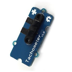
Digital Tachometer RPM , Speed or Pulse counting Sensor Module. Can be used with Arduino, Raspberry Pi and other microcontroller boards.
Applications
- RPM Sensing, Speed Sensing
- As Home and End limit sensor in CNC machines
- Position Detection Sensor
- Pulse counting
Features
- Output state indicator LED (LED ON means No obstruction)
- Power state indicator LED
- 3.3V and 5V logic level compatibility
- 4 pin standard male header for interfacing with electronics
- A fixed hole for easy installation
- Built in LM393 comparator for perfect non-intermediate logic low and high output
- The use of quality coupler slot sensor
Technical Specifications
- Operating voltage: 3.3V-5V
- Maxim Output Drive: 15mA
- Digital Output (DO) Output Low : When No Obstruction
- Digital Output (DO) Output High: When Obstructed
- Analog Output: Near 0V when no obstruction, between 0V and VCC when less obstruction and Near VCC when full Obstruction
- Header Pitch: Standard 0.1 inch (2.54mm)
- Grove width : 5mm
- PCB Size: 3.2cm x 1.4cm
- Mounting Hole Diameter: 3.0mm
Pinouts
- VCC
- GND
- DO (Digital Out)
Getting started with the Digital Tachometer Speed Module Sensor
Tachometer is a simple module that allow you to test the speed of the motor. Widely used for motor speed detection, Pulse count, position limit, and so on.
Hardware required
- Arduino UNO
- Digital Tachometer Speed Module Sensor
- Jumper wires
Connecting the Hardware

Code:
int encoder_pin = 2; // pulse output from the module
unsigned int rpm; // rpm reading
volatile byte pulses; // number of pulses
unsigned long timeold;
// number of pulses per revolution
// based on your encoder disc
unsigned int pulsesperturn = 12;
void counter()
{
//Update count
pulses++;
}
void setup()
{
Serial.begin(9600);
pinMode(encoder_pin, INPUT);
//Interrupt 0 is digital pin 2
//Triggers on Falling Edge (change from HIGH to LOW)
attachInterrupt(0, counter, FALLING);
// Initialize
pulses = 0;
rpm = 0;
timeold = 0;
}
void loop()
{
if (millis() – timeold >= 1000) {
//Don’t process interrupts during calculations
detachInterrupt(0);
rpm = (60 * 1000 / pulsesperturn )/ (millis() – timeold)* pulses;
timeold = millis();
pulses = 0;
Serial.print(“RPM = “);
Serial.println(rpm,DEC);
//Restart the interrupt processing
attachInterrupt(0, counter, FALLING);
}
}
RESULTS
open your serial monitor by clicking on the icon in the right top corner(like search icon) .


