")
Description
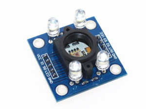
The TCS3200 Color Recognition Sensor Module uses a high-quality light sensor allowing you to sense any color through a combination of Red, Green, and Blue. The module provides all of the pins of the TCS3200 on convenient 0.1″ headers – ideal for use with PCBs, breadboard or stripboard.
Specification
- Operating Voltage: 3V-5V
- High-resolution conversion of light intensity to frequency.
- Chip pins all has drawn for standard 100.
- Put the needle (2.54 mm).
- Mil-convenient for bitmap board.
- Programmable color and full-scale output frequency.
- Communicate directly with a microcontroller.
- Best Detection Range: 10mm.
The pinout is clearly labeled on the board and is as follows
Header one on the left side of the board
- S0: Output frequency scaling selection input (along with S1)
- S1: Output frequency scaling selection input (along with S0)
- OE: Output Enable – if held low, the output of the module is turned on
- GND: Ground – connect to 0V
Header two on the right side of the board
- S3: Photodiode type (along with S2)
- S2: Photodiode type (along with S3)
- OUT: Output – A square wave appears here showing the intensity of the detected colour
- VCC: Power – connect to 2.7V-5.5V
The Photodiode type pins allow you to pick which color light you are currently detecting:
S2 S3 Photodiode type
Low Low Only red light
Low High Only blue light
High Low No filter
High green light
By combining the reading of each of the three colors, you can identify any visible color!
Getting started with the Color sensor TCS230 TCS3200 color Recognition Sensor Detector module DC 3-5V input for arduino
This project is used for detecting primary colors (red, green and blue). The project demonstrates the basic interfacing of TCS3200 sensor, Arduino Uno .
Color Sensor TCS230 TCS3200 is a complete color detector, including a TAOS TCS3200 RGB sensor chip and 4 white LEDs. The TCS3200 can detect and measure a nearly limitless range of visible colors. Applications include test strip reading, sorting by color, ambient light sensing and calibration, and color matching, to name just a few.
The TCS3200 GBB Color Sensor For Arduino has an array of photo detectors, each with either a red, green, or blue filter, or no filter (clear). The filters of each color are distributed evenly throughout the array to eliminate location bias among the colors. Internal to the device is an oscillator which produces a square-wave output whose frequency is proportional to the intensity of the chosen color.
Hardware required
Connecting the Hardware
Here’s the connections between the TCSP3200 and the Arduino:
- S0: digital pin 3
- S1: digital pin 4
- VCC: 5V
- S3: digital pin 6
- S2: digital pin 5
- OUT: digital pin 2
- GND:GND

Upload the sample sketch
S0, S1, S2, S3
To TCS3002D, when choose a color filter, it can allow only one particular color to get through and prevent other color. For example, when choose the red filter, Only red incident light can get through, blue and green will be prevented. So we can get the red light intensity. Similarly ,when choose other filters we can get blue or green light.
TCS3002D has four photodiode types. Red , blue, green and clear, reducing the amplitude of the incident light uniformity greatly, so that to increase the accuracy and simplify the optical. When the light project to the TCS3002D we can choose the different type of photodiode by different combinations of S2 and S3. Look at the form as follows.
| S0 | S1 | OUTPUT FREQUENCY SCALING (fo) |
|---|---|---|
| L | L | Power down |
| L | H | 2% |
| H | L | 20% |
| H | H | 100% |
TCS3002D can output the frequency of different square wave (occupies emptiescompared 50%),different color and light intensity correspond with different frequency of square wave. There is a relationship between the output and light intensity. The range of the typical output frequency is 2HZ~500KHZ. We can get different scaling factor by different combinations of S0 and S1. Look at the form as follows.
| S2 | S3 | PHOTODIODE TYPE |
|---|---|---|
| L | L | RED |
| L | H | BLUE |
| H | L | Clear (no filter) |
| H | H | GREEN |
Sample Code
int s0=3,s1=4,s2=5,s3=6;
int out=2;
int flag=0;
byte counter=0;
byte countR=0,countG=0,countB=0;
void setup()
{
Serial.begin(115200);
pinMode(s0,OUTPUT);
pinMode(s1,OUTPUT);
pinMode(s2,OUTPUT);
pinMode(s3,OUTPUT);
}
void TCS()
{
flag=0;
digitalWrite(s1,HIGH);
digitalWrite(s0,HIGH);
digitalWrite(s2,LOW);
digitalWrite(s3,LOW);
attachInterrupt(0, ISR_INTO, CHANGE);
timer0_init();
}
void ISR_INTO()
{
counter++;
}
void timer0_init(void)
{
TCCR2A=0x00;
TCCR2B=0x07; //the clock frequency source 1024 points
TCNT2= 100; //10 ms overflow again
TIMSK2 = 0x01; //allow interrupt
}
int i=0;
ISR(TIMER2_OVF_vect)//the timer 2, 10ms interrupt overflow again. Internal overflow interrupt executive function
{
TCNT2=100;
flag++;
if(flag==1)
{
countR=counter;
Serial.print(“red=”);
Serial.println(countR,DEC);
digitalWrite(s2,HIGH);
digitalWrite(s3,HIGH);
}
else if(flag==2)
{
countG=counter;
Serial.print(“green=”);
Serial.println(countG,DEC);
digitalWrite(s2,LOW);
digitalWrite(s3,HIGH);
}
else if(flag==3)
{
countB=counter;
Serial.print(“blue=”);
Serial.println(countB,DEC);
Serial.println(“\n”);
digitalWrite(s2,LOW);
digitalWrite(s3,LOW);
}
else if(flag==4)
{
flag=0;
}
counter=0;
}
void loop()
{
TCS();
while(1);
}
Result