Description
The AD8232 ECG measurement Heart rate Monitor is a cost-effective board used to measure the electrical activity of the heart. This electrical activity can be charted as an ECG or Electrocardiogram and output as an analog reading. ECGs can be extremely noisy, the AD8232 Single Lead Heart Rate Monitor acts as an op amp to help obtain a clear signal from the PR and QT Intervals easily.
The AD8232 is an integrated signal conditioning block for ECG and other biopotential measurement applications. It is designed to extract, amplify, and filter small biopotential signals in the presence of noisy conditions, such as those created by motion or remote electrode placement.
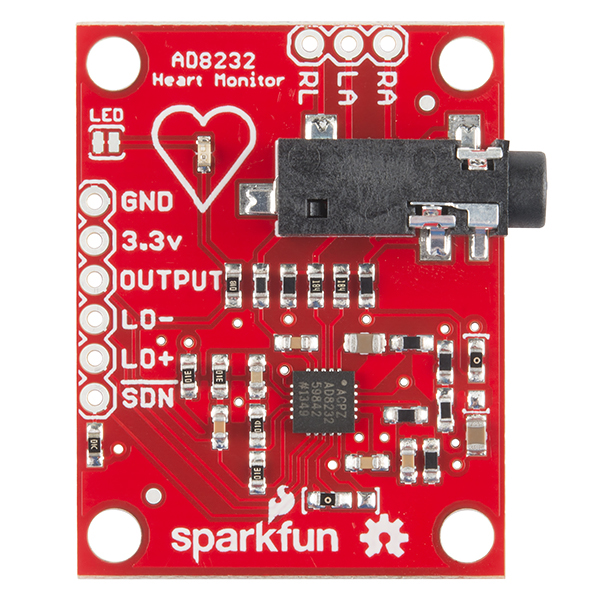
The AD8232 Heart Rate Monitor breaks out nine connections from the IC that you can solder pins, wires, or other connectors to. SDN, LO+, LO-, OUTPUT, 3.3V, GND provide essential pins for operating this monitor with an Arduino or other development board. Also provided on this board are RA (Right Arm), LA (Left Arm), and RL (Right Leg) pins to attach and use your own custom sensors. Additionally, there is an LED indicator light that will pulsate to the rhythm of a heart beat. Biomedical Sensor Pads and Sensor Cable are required to use the heart monitor.
Specifications and pin connection:
- Operating Voltage – 3.3V
- Analog Output
- Leads-Off Detection
- Shutdown Pin
- LED Indicator
- 3.5mm Jack for Biomedical Pad Connection

Circuit Diagram
Follow the diagram below, to make necessary connections. The SDN pin is not used in this demo. Connecting this pin to ground or “LOW” on a digital pin will power down the chip. This is useful for low power applications.

ECG Module Arduino
GND GND
3.3V 3.3V
OUTPUT A5
LO- D2
LO+ D3
After making connection diagram, connect 3.5mm biomedical three electrode pad connectors with black colour female jack. This electrode pad comes with colour coding such as:
Red: RA (Right Arm)
Yellow: LA (Left Arm)
Green: RL (Right Leg)
It is recommended to snap the sensor pads on the leads before application to the body. The closer to the heart the pads are, the better the measurement.

Arduino code:
void setup() {
// initialize the serial communication:
Serial.begin(9600);
pinMode(3, INPUT); // Setup for leads off detection LO +
pinMode(2, INPUT); // Setup for leads off detection LO –
}
void loop() {
if((digitalRead(10) == 1)||(digitalRead(11) == 1)){
Serial.println(‘!’);
}
else{
// send the value of analog input 0:
Serial.println(analogRead(A5));
}
//Wait for a bit to keep serial data from saturating
delay(1);
}
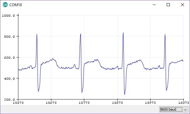
Results
After uploading code, you can visualize the output in the form graph on Arduino IDE plotter. In Arduino IDE, go to tools>Serial Plotter and set the baud rate to 9600. After that you will see an output like this on Arduino serial plotter.