Description
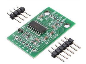
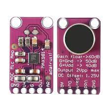
The MAX9814 microphone amplifier module is a high-performance, low-noise amplifier with built-in automatic gain control (AGC). It is designed for audio applications such as voice detection, sound measurement, and voice-activated systems. The module features a built-in MAX9814 IC, a high-quality electret microphone, and supports adjustable gain control.
Ideal for use with Arduino and other microcontrollers, it provides clean analog audio output, even when the sound level varies greatly.
Features
- Built-in MAX9814 amplifier chip
- Automatic Gain Control (AGC) for consistent output levels
- Wide supply voltage: 2.7V – 5.5V
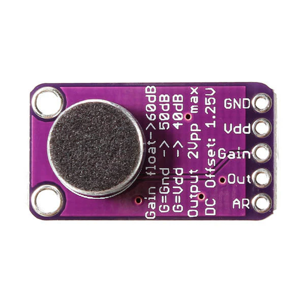
- Adjustable gain: 40dB, 50dB, 60dB (via pin jumper)
- Output: Analog audio signal
- High sensitivity and low noise
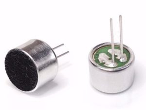
- Compact PCB with onboard electret microphone
Getting started with MAX9814 Microphone amplifier Module AGC
In this project we are going to demonstrate how to use the MAX9814 microphone amplifier module with an Arduino to create a sound-reactive LED. The LED’s brightness changes in response to detected sound levels, creating a simple audio visualization effect. Feel free to go beyond this example, even including Machine Learning (ML).
Hardware Requirements
- Arduino board (Uno, Nano, or compatible)
- MAX9814 microphone amplifier module
- LED (built-in or external)
- Current-limiting resistor (220-330Ω for external LED)
- Breadboard
- and jumper wires
Connections
- MAX9814 to Arduino:
- OUT → A0
- VDD → 5V
- GND → GND
- GAIN pin settings:
- Ground (GND) = 40dB gain
- VDD (5V) = 50dB gain
- Floating = 60dB gain (default)
- LED:
- Connect to a PWM-capable pin (suggested pins: 3, 5, 6, 9, 10, or 11)
- Remember to use a current-limiting resistor (220-330Ω)
- Example: LED positive → pin 9, LED negative → GND via resistor
Project Codes
- Cope the codes
- Open sketch in Arduino IDE
- Upload the sketch to your Arduino board
Installation


- Power up your Arduino
- The LED will respond to sound:
- Louder sounds = Brighter LED
- Quieter sounds = Dimmer LED
- Visualization options:
- Serial Monitor (9600 baud): View raw sensor values
- Serial Plotter (9600 baud): View real-time graphs of:
- Raw signal (blue)
- Mapped LED brightness (red)
- Moving average (green)

Applications
- Voice detection
- Audio level monitoring
- DIY sound-reactive lights
- Voice-controlled interfaces
- Noise detection and logging