Description
Features
- Quad-band 850/900/1800/1900MHz
- GPRS multi-slot class12 connectivity: max. 85.6kbps (down-load/up-load)
- GPRS mobile station class B
- 3GPP TS 27.007, 27.005 and SIMCOM enhanced AT Commands
- Real Time Clock
- Power voltage 3.4V ~ 4.4V DC
- A-GPS (Assisted Global Positioning System)
- Supports 2.8V to 5.0V logic level
- Low power consumption, 1mA in sleep mode
- Compact size 23mm x 35mm x 5.6mm
- Standard SIM Card
How to get started with small SIM800l GSM module
Introduction
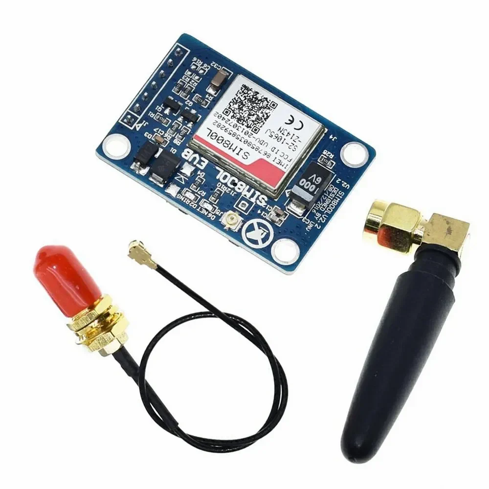
Mini GSM / GPRS breakout board is based on SIM800L module, supports quad-band GSM/GPRS network, available for GPRS and SMS message data remote transmission.
The board features compact size and low current consumption. With power saving technique, the current consumption is as low as 1mA in sleep mode. It communicates with microcontroller via UART port, supports SIMCOM enhanced AT Commands.
Overview
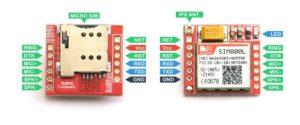
Pinout description
There are 12 total pins on the small SIM800L two parallel rows of six headers. One row contains all of the pins required to interface with Arduino, the other row has all things for interface.
- GND: Ground for SIM800L
- VCC: Supply Voltage input for SIM800L
- RST: Reset pin for SIM800L
- RXD: Serial communication (Receiver Pin)
- TXD: Serial communication (Transfer Pin)
- NET: Antenna
- RING: Low state while receiving call
- DTR: Sleep mode
- MICP: Microphone +
- MICN: Microphone –
- SPKP: Speaker +
- SKPN: Speaker –
Hardware Required
- Small SIM800L
- Micro Sim
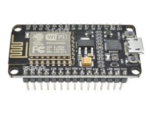
- Arduino Uno R3
- Solderless Breadboard
- Jumper Wires
- DC-DC Adjustable Step down Module
- 1kOhm resistor
- NPN transistor (we used BC 547)
Step 1. Hardware Setup
From the specification of SIM800L we would able to find out that is:
- Operating voltage: 3.3 – 5 Volts
- Recommended voltage: 3.4 – 4.4 Volts
- Recommended Current: 1 – 2 Amps
- Recommended Power: 5 Watts
Therefore, if we use voltages below 3.4, either the SIM800l will not work or it will work but not all its features are responding (e.g unable to read SIM card). But if we use voltage equal to its MAXIMUM operating voltage, the module might heat up and then get destroyed, or if we use ABOVE operating voltage, it will absolutely destroy the module, Most important, we should not supply a current above 2 Amp (e.g 3-5 Amp) to the module, it will destroy the module even if your voltage is in 3,4 – 4.4 volts range
We will set SIM800L up with Arduino to send simple text message. There are two ways to do this:
- First way: Using an external power supply
- Second way: using Arduino pin to supply the SIM800l
Note: The second way is easy but does not work for every arduino board, It will be nice if you stick it up with the first way as to be sure your SIM800L register to a network as quick as possible.
First Way
Let starts by regulating the voltages from our AC-DC power, we need to connect it to the DC-DC step down module like this.
- AC-DC power VCC (+) ↔ DC-DC step down IN + .
- AC-DC power GND (-) ↔ DC-DC step down IN – .
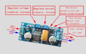
Turn the indicated screw anti-clockwise until you get the desired voltage ( between 3.4 -4.4 volts) by measuring it with a voltmeter connected onto the output leads of the module. Then regulate the current by turning anti-clockwise and connect the voltmeter leads and measure the output current.
When the LED on the DC-DC module light up in blue, this indicates the maximum short circuit current, You must not worry about it being 2 Amps and some decimal. After that try connecting any resistor not exceeding 1k Ohm in series with the multimeter and measure the current. The values you get is the same as the current that will be used by SIM800L module.
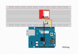
Hook up
We will hook up the SIM800L module with Arduino using the SoftwareSerial library present in new version later than Arduino IDE 1.0.1. We will connect Hardware serial port to thecomputer to debug and print messages.
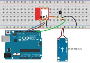
Connect the SIM800L pins like this:
- SIM800L GND ↔ DC-DC step down OUT –
- SIM800L TX ↔ Arduino D10
- SIM800L RX ↔Arduin D11
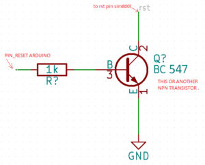
- SIM800L RST ↔ Arduino D02 (through the circuit shown below)
- SIM800L VCC ↔ DC-DC step down OUT +
Note that the module requires voltage in range of 3.4 to 4.4v. If proper voltage is not provided the module will give under and over voltage warnings. Also another thing is that if you have a 3.7v 1000mAh LiPo battery, you can also power up you SIM800L with it.
The SIM800 LED indicator will blink once every 2 or 3 seconds when it has completely registered your Sim to a network, when the LED indicator is blinking every second once, this means that the SIM800L is still searching for a network to register onto. When the LED indicator does not blink, your power supply do provide low current even if you calibrated well the voltage.
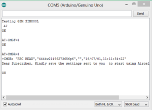
Test code
Let us start with the simple text code that will verify if everything is setup properly. Remember to insert a SIM card before proceeding further. The code below takes commands from the Arduino terminal and sends it to the GSM Module. It also sends the commands other way around, from the GSM module to the Arduino. The code will also verify if the Software Serial library is also working fine.
once you upload the code to your Arduino board, you’ll be able to send all AT command in order to send/receive text messages or make calls.
Sending SMS
We will now use the basic sim800l library to send messages. the code asks you to enter phone number and the message to be sent and sends the message!
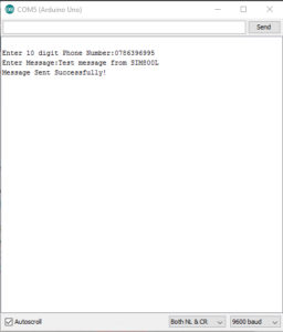
If you get an error message please go up and fix where you made a mistake.
Second Way
Like in the first way we are going to send an SMS using SIM800L. You might ask why we are going to power up the SIM800L with arduino 5V pin and say that’s sound risky, but as we know 5V pin on Arduino generate current from 500mA- 1 Amp (not all Arduino board do, here we used Arduino Genuino UNO R3 ) which gives a maximum power of 5 watts. 5 watts qualifies from recommended power which would not cause the module to heat up or being destroyed. That’s why 5V pin on Arduino qualifies as a supply voltage.
Step 1. Circuit Connection
Note: Make sure you already inserted your SIM card before powering the module. If not, you will not see any changes in the module LED indicator.
- SIM800 VCC ↔ Arduino 5v
- SIM800 GND ↔ Arduino GND
- SIM800 SIM_TXD ↔ Arduino pin 3
- SIM800 SIM_RXD ↔ Arduino pin 2
Note: if SIM800L LED indicator blink once every 2 or 3 seconds, your SIM already boot up and registered to a network. If not, try checking your SIM if it is properly in place. If SIM800L LED indicator blink once every second, the SIM800L is trying t get connected to your SIM card network provider wait until you get connected or just reboot the module by removing the VCC pin from the Arduino the back again until the LED blinks once every 3 seconds.
Step 3: Code
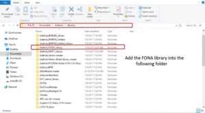
- Download and Add Adafruit Fona library to your Arduino library.
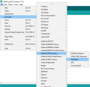
- Then open and upload the FonaTest sample code from Adafruit Fona example.
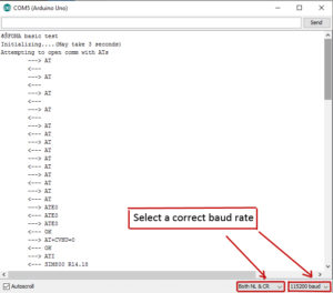
- Open Serial monitor the change baudrate to 115200 and choose Both NL & CR
- then you’ll see Menu of test setup; choose anything you want to test (e.g Send and receive message).
Then browse into the Adafruit FONA library’s sample test code and find FONAtest and upload to your Arduino.
Open your serial monitor and select a correct baud rate wait for the SIM800L to respond.
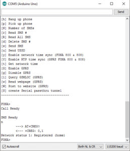
Then check for your network status or if your SIM has completely register to a network. do it by typing n in the serial monitor.
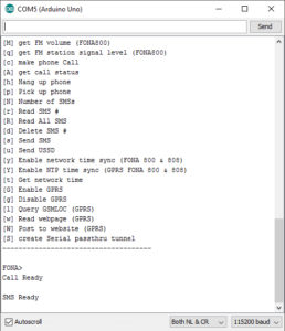
Follow the drop list to send or receive the message or try other commands you want.
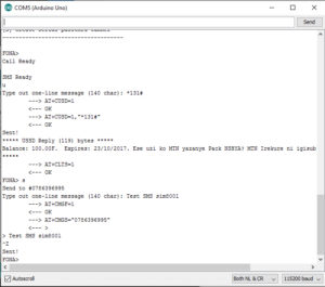
Sending SMS
Type in s and fill in with the phone number, then write a message you want to send (less tha 140 charcter) and press Return(enter) then wait for the message for the target handset. if you don’t receive the sms, you will get an error message on the serial monitor. If that’s not the case wait until you receive the message. refer to the below images.
Resources
Documents and Library:
Arduino Code:
Package includes:
1×Smallest SIM800L With Antenna