Description
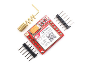
The SIM800L module is a complete Quad-band GSM/GPRS solution in a LGA type which can be embedded in the customer,it has a set of TTL level serial interface, a set of power supply interface. Besides, there are a set of antenna interface on this module.
Features
- Supply voltage range 3.4 ~ 4.4V and
- Current of 1A or more(the current is very important)
- It features Bluetooth, FM and Embedded AT(AT commands)
- Quad-band 850/900/1800/1900MHz
- Operation temperature:-40 ~85 degree celcius
Applications:
- SIM800L support Quad-band 850/900/1800/1900MHz, it can transmit Voice, SMS and data information with low power
- Due to its size,It can fit into slim and compact demands of customer design.
How to get started with SIM800L GSM module
This SIM800L module supports quad-band GSM/GPRS network, available for GPRS and SMS message data remote transmission. SIM800L is one of the most commonly used GSM module among hobbyists and Arduino community. It is not very easy for a beginner to properly understand and use Arduino with SIM800L. Therefore, this post summarizes how a beginner could interact with SIM800 using Arduino. On the back it has a simslot on which you insert a micro-Sim. When it is receiving enough power the power LED on board must light.
Overview
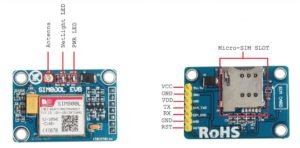
Pinout Description
There are 7 total pins on the SIM800L, which we are going to use to interface with Arduino.
- VCC: External Supply Voltage input for SIM800L
- GND: External Ground for SIM800L
- VDD: MicroContrroller Supply voltage input for SIM800L
- RST: Reset pin for SIM800L
- RXD: Serial communication (Receiver Pin)
- TXD: Serial communication (Transfer Pin)
Hardware Required
- SIM800L ver. 2
- Micro Sim
- Arduino Uno R3
- Solderless Breadboard
- Jumper Wires
- DC-DC Adjustable Step down Module
Hardware Setup
From the SIM800L datasheet, we would be able to find out that it consumes the following:
- Operating Voltages: 3.6 – 5.20 Volts
- Operating Current: 1-2.5 Amps
If you supply Voltage less than 4.6v, the SIM800L will not power up and work. Since this SIM800L is a good power hungry module, we will supply it with 5.20v as it’s can operate at this voltage without heating or get destroyed. One most important thing to keep inmind is that, it is a massive power hungry module hence we need an external power supply to get it working. The module consumes much of its power when it is searching for a network and sending and receiving data from a network carrier. we should not supply a current above 2.5 Amp (e.g 3-5 Amp) to the module, it will destroy the module even if your voltage is in 4.6 – 5 volts range.
We will set SIM800L up with Arduino to send simple text message and make a voice call. Let starts by regulating the voltages from our AC-DC power, we need to connect it to the DC-DC step down module like this.
- AC-DC power VCC (+) ↔ DC-DC step down IN + .
- AC-DC power GND (-) ↔ DC-DC step down IN – .
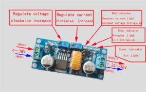
Turn the indicated screw anti-clockwise until you get the desired voltage ( between 4.9 – 5.25 volts) by measuring it with a voltmeter connected onto the output leads of the module. Then regulate the current by turning anti-clockwise and connect the voltmeter leads and measure the output current.
When the LED on the DC-DC module light up in blue, this indicates the maximum short circuit current, You must not worry about it being more than the required Amp. Adjust the current to the desired amp (between 2.20 – 2.40 amps). Once you have go the right amp and voltages, now it’s tome to do the circuit between arduino and the SIM800L.
Note: when powering the SIM800L you may use other voltage regulator like LM317 but you must make sure you get the voltages and amps in the above specified range.
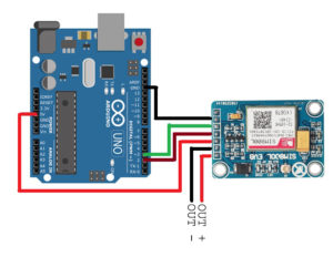
Wiring
For above module Arduino to SIM800 connectivity was pretty straight forward .
- SIM800L VDD ↔ Arduino 5v
- SIM800L GND (UART TTL) ↔ Arduino GND
- SIM800L SIM_TXD ↔ Arduino D2 (read through for the reason)
- SIM800L SIM_RXD ↔ Arduino D3 (read through for the reason)
- SIM800L 5VIN (POWER) ↔ External Positive Power Supply pin
- SIM800L GND (POWER) ↔ External Negative Power Supply pin
Before we go into the code make sure you made the external power supply voltage and amps as specified above without it the module will not function as intended and insert your Micro-Sim into that slot before powering it up.
The SIM800L LED indicator will blink once every 2 or 3 seconds when it has completely registered your Sim to a network, when the LED indicator is blinking every second once, this means that the SIM800L is still searching for a network to register onto. When the LED indicator does not blink, your power supply do provide low current even if you calibrated well the voltage.
Arduino code
Let us start with the simple Test code that will verify if everything is setup properly. Remember to insert a SIM card before proceeding further. The code below takes commands from the Arduino terminal and sends it to the GSM Module. It also sends the commands other way around, from the GSM module to the Arduino. Once you upload the code to your Arduino board, you’ll be able to send all AT command in order to send/receive text messages or make calls.
Sending SMS and Making Voice-call
This simple Arduino code will send a text message to a mobile handset or make a voice voice call. You only have to type in ‘s’ for sending SMS text or ‘c’ for voice calling.
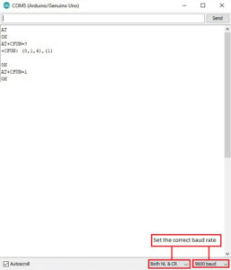
Here is how your serial monitor should look like:
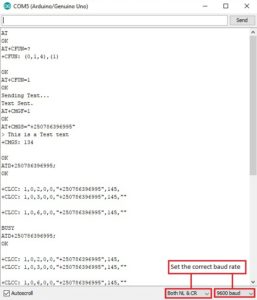
Note: don’t forget to set a correct baud rate (9600 and Both NL & CR, also fill in the number of your mobile handset on the following lines:
sim800l.print(“AT+CMGS=”+2507*******”r”);
sim800l.println(“ATD+25078*******;”);
Another thing to wait onto is the initialization of the SIM800L which takes a couple of seconds, usually less than a minutes hence your SIM800L have been registerd onto a network you can type in ‘s’ and send a test message or ‘c’ to dial a number.
Resources
Send SMS and Voive Call Sketch
Package includes:
1×SIM800L V2.0 With Antenna