Description
This Arduino sensor kit is the best for beginners to link our daily environment with modern technology by using Arduino and it’s compatible sensors. Brand new 37 sensors in 1 Sensor Kits for Arduino
Package Included:
- 1 x Joystick sensor
- 1 x Relay module
- 1 x Big sound sensor
- 1 x Small sound sensor
- 1 x Tracking sensor
- 1 x Avoid sensor
- 1 x Passive buzzer
- 1 x Active buzzer
- 1 x Digital temperature
- 1 x Metal touch sensor module
- 1 x Linear hall
- 1 x Flame
- 1 x RGB LED
- 1 x SMD RGB LED
- 2 x Two-color LED
- 1 x Reed switch
- 1 x Mini Reed
- 1 x Rotary encoders
- 1 x Shock
- 1 x Button
- 1 x laser emit
- 1 x 7 color flash
- 1 x Heartbrat
- 1 x Light Cup
- 1 x Tilt switch
- 1 x Ball Switch
- 1 x Photoresistor
- 1 x temp and humidity
- 1 x analog Hall
- 1 x tap module
- 1 x Light blocking
- 1 x IR receiver
- 1 x IR emission
- 1 x Analog temp
- 1 x temp 18B20
- 1 x Hall magnetic
Getting started with the Sensor Kit
All the experiments in this Sensor kit are done with Arduino Uno R3 board, but they are also compatible with Arduino Mega 2560, Arduino Nano and all official Arduino Boards. All the code included in this Sensor kit works with these boards.
This Sensor kit is different from other kits. All the components in this kit are provided in the form of modules which integrate some necessary components, such as comparator, resistor, and capacitor and so on. Therefore it is convenient for circuit connection.
1. Joystick sensor
A joystick is an input device consisting of a stick that pivots on a base and reports its angle or direction to the device it is controlling. Joysticks are often used to control video games and robots.
In this experiment, we use the Arduino Uno board to detect the moving direction of the Joystick knob and pressing of the button.

Hardware required
- Arduino Uno
- Joystick sensor
- Jumper wires
Connecting the Hardware
Joystick sensor Arduino UNO
- SW D8
- VRx A0
- VRy A1
- +5V 5V
- GND GND

CODE
The program is very simple. We will read the measurement from two analog inputs and one digital input. Then we will display the result on serial monitor.
const int xPin = A0;
const int yPin = A1;
const int swPin = 8;
void setup()
{
pinMode(swPin,INPUT);
digitalWrite(swPin, HIGH);
Serial.begin(9600);
}void loop()
{
Serial.print(“X: “);
Serial.print(analogRead(xPin),DEC);
Serial.print(“|Y: “);
Serial.print(analogRead(yPin),DEC);
Serial.print(“|Z: “);
Serial.println(digitalRead(swPin));
delay(500);
}
RESULTS
Now, push the rocker and the coordinates of X and Y axes displayed on Serial Monitor will change accordingly; press the button, and the coordinate of Z will also be displayed. If everything is fine, you should see below output on serial monitor.

2. Relay module
Relays are suitable for driving high power electronic devices such as lights, electric fans and air condition. A relay can be used to control high voltages with a low voltage by connecting it to an MCU. Connect IO to the Arduino Uno board. When we make the transistor output low level (0V) by programming, the transistor will conduct electricity because of current saturation. The normally open contact of the relay will be closed, while the normally closed contact of the relay will be opened; when it outputs high level (5V), the transistor will be cut off, and the relay will restore to the initial state.

Hardware required
- Arduino UNO
- Relay module
- Bulb
- Jumper wires
Connecting the Hardware
| Relay module | Arduino Uno |
| s | 8 |
| “-” | GND |
| + | 5V |

Code
const int relayPin =8; //the “s” of relay module attach to
void setup()
{
pinMode(relayPin, OUTPUT); //initialize relay as an output
}
void loop()
{
digitalWrite(relayPin, HIGH); //Close the relay
delay(1000); //wait for 1 second
digitalWrite(relayPin, LOW); //disconnect the relay
delay(1000); //wait for 1 second
}
Results
Now, you may hear ticktock. That’s the normally closed contact opened and the normally open contact closed.
3: Big sound sensor/Small sound sensor
There are two kinds of microphone sensor in this kit: microphone sensor and high-sensitive voice sensor (as shown below). The only difference between them is sensitivity. In this experiment, we will take the microphone sensor for example. You may try to apply the other sensor based on what you’ve got during the process.
Both sensors have two outputs:
AO: analog output, to output voltage signals from microphone in a real-time manner
DO: When sound intensity reaches a certain threshold, the sensor outputs high or low level (you can adjust the threshold by potentiometer)

Microphone Sensor High-sensitive Voice Sensor
Hardware required
– Arduino Uno board
– Big sound sensor module
– Jumper wires
Experimental Principle
Microphone can convert audio signal into electrical signal (analog quantity), then convert analog quantity into digital value by ADC and transfer it to MCU to process.
Connecting the Hardwar
Microphone Sensor Module Arduino Uno
AO —————— ———————- A0
G ——————— ——————– GND
+ —————— ———————– 5V

Code for Microphone
const int ledPin = 13; //the led attach to
const int soundPin = A0;void setup()
{
pinMode(ledPin,OUTPUT);
Serial.begin(9600);
}void loop()
{
int value = analogRead(soundPin);
Serial.println(value);
if(value > 30)
{
digitalWrite(ledPin,HIGH);
delay(200);
}
else
{
digitalWrite(ledPin,LOW);
}
}
Code for High-sensitive Voice Sensor
const int ledPin = 13;
const int soundPin = A0;void setup()
{
pinMode(ledPin,OUTPUT);
Serial.begin(9600);
}void loop()
{
int value = analogRead(soundPin);
Serial.println(value);
if(value > 25)
{
digitalWrite(ledPin,HIGH);
delay(20000);
}
else
{
digitalWrite(ledPin,LOW);
}
}
RESULTS
Now, speak near or blow into the microphone, and you can see the LED attached to pin 13 on the Arduino Uno board brighten.
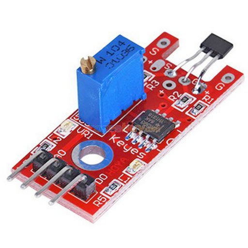
4. Tracking sensor
A tracking sensor (as shown below) has the same principle with an obstacle avoidance sensor but has small transmitting power.

Working of the sensor:
So what I have here actually is a test track that I had made for the line tracking sensor or Line Following Sensor and I have got some lines that are made by a marker and then I have got one line that’s made out of electrical tape. I just wanted to see how the sensor does in different conditions with different materials. So let’s go ahead when I put it on a black surface it goes blank and goes in a white surface gives me a blue light.
Experimental Principle
When the infrared transmitter emits rays to a piece of paper, if the rays shine on a white surface, they will be reflected and received by the receiver, and pin (OUT) will output low level; If the rays encounter black lines, they will be absorbed, thus the receiver gets nothing, and pin (OUT) will output high level. Since an LED has been attached to pin 13, connect the pin out to D8 of the Arduino Uno board. When the tracking sensor detects reflection signals (white), the LED will be on. Otherwise, it will be off (black line).
Hardware required
- Arduino Uno
- Tracking line sensor
- Led
- Jumper wires
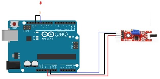
Connecting the Hardware
![]()
Code
const int tracingPin = 8;
const int ledPin = 13;
void setup()
{
pinMode(tracingPin, INPUT);
pinMode(ledPin, OUTPUT);
}void loop()
{
int val = digitalRead(tracingPin);
if(val == HIGH)
{
digitalWrite(ledPin, HIGH);
}
else
{
digitalWrite(ledPin, LOW);
}
}
RESULTS
A few seconds after the upload finishes, set it down on a piece of paper with a dark line (at least ½” wide). You may use a Sharpie Marker, electrical tape, or dark paint. When the module gets on a black line, the LED attached to pin 13 on Arduino Uno board will light up. Otherwise; when it meets a white area, the LED turns Off.
5. Avoid sensor
An Obstacle Avoid Sensor (as shown below) uses infrared reflection principle to detect obstacles. When there is no object in front, infrared-receiver can not receive signals; when there is an object in front, it will block and reflect infrared light, then infrared-receiver can receive signals.

Experimental Principle
An avoidance sensor mainly consists of an infrared-transmitter, an infrared-receiver and a potentiometer. According to the reflecting character of an object, if there is no obstacle, emitted infrared ray will weaken with the propagation distance and finally disappear. If there is an obstacle, when infrared ray encounters an obstacle, it will be reflected back to the infrared-receiver. Then the infrared-receiver detects this signal and confirms an obstacle exists in front.
In this experiment, we will use an avoid sensor module and an LED attached to pin 13 of the Arduino UNO to build a simple circuit. When the Avoid sensor detects an obstacle, the LED will be on. Otherwise, it will be off.
Note: The Avoid distance of infrared sensor is adjustable; you can adjust the obstacle avoidance distance by adjusting the potentiometer.
Hardware required
- Avoid sensor
- Arduino UNO
- Jumper wires
Connecting the Hardware
Avoid Sensor Arduino Uno
out ————————————– D2
GND—————————————- GND
VCC —————————————- 5V

In this experiment, we will use an avoid sensor module and an LED attached to pin 13 of the Arduino UNO to build a simple circuit. With the LED attached to pin 13, connect pin OUT to D2 of the Arduino UNO . When the Avoid sensor detects an obstacle, the LED will be on. Otherwise, it will be off.
Code
int LED = 13;
int isObstaclePin = 2;
int isObstacle = HIGH;
void setup() {
pinMode(LED, OUTPUT);
pinMode(isObstaclePin, INPUT);
Serial.begin(9600);
}
void loop() {
isObstacle = digitalRead(isObstaclePin);
if (isObstacle == LOW)
{
Serial.println(“OBSTACLE!!, OBSTACLE!!”);
digitalWrite(LED, HIGH);
}
else
{
Serial.println(“clear”);
digitalWrite(LED, LOW);
}
delay(200);
}
RUNNING RESULT
A few seconds after the upload finishes, place a board in front of the Obstacle Avoidance Sensor, and the LED attached to pin 13 on the Arduino Uno board will light up, the on-board obstacle led will turn on. It will turn off when there is no obstacle.
At the same time, choose the corresponding port type for you Arduino board and open the Serial Monitor of the Arduino IDE, make sure the baudrate is same as your code, move the obstacle in front of the Obstacle Avoidance Sensor, you will see the serial output as below:

7.Passive buzzer module
This is a passive piezo buzzer module useful for creating sound in a project. There are two types of buzzers, passive buzzers such as this one and active buzzers.
Passive buzzers are similar in function to a small speaker and need to be driven by a waveform with enough drive current capability to create the desired sound. This is typically done using PWM from an MCU. The advantage of a passive buzzer is that the tone and loudness of the buzzer can be controlled by the frequency and drive power of the waveform that is used to drive it.

Experimental Principle
it can produce a range of sound tones depending on the input frequency.
Hardware required
- Passive buzzer
- Arduino UNO
- Jumper wire
Connecting the Hardware
Connect signal (S) to pin 8 on the Arduino and ground (-) to GND. The middle pin is not used.

Code for Passive
int buzzer = 8;
void setup() {
pinMode(buzzer, OUTPUT);
}
void loop() {
for (int i = 0; i < 80; i++) {
digitalWrite(buzzer, HIGH); // send high signal to buzzer
delay(1); // delay 1ms
digitalWrite(buzzer, LOW); // send low signal to buzzer
delay(1);
}
delay(50);
for (int j = 0; j < 100; j++) { //make another sound
digitalWrite(buzzer, HIGH);
delay(2); // delay 2ms
digitalWrite(buzzer, LOW);
delay(2);
}
delay(100);
}
RESULTS
The following Arduino sketch will generate two different tones by turning on and off the Passive buzzer at different frequencies using a delay.
8. Active buzzer module
The active buzzer has built-in oscillating source, so it will beep as long as it is electrified, but it can only beep with a fixed frequency.

Experimental Principle
The KY-012 Active Buzzer module consists of an active piezoelectric buzzer, it generates a sound of approximately 2.5kHz when signal is high.
Hardware required
- Active buzzer
- Arduino UNO
- Jumper wire
Connecting the Hardware
Connect signal (S) to pin 8 on the Arduino and Ground (-) to GND. Be aware that some boards are wrongly labeled, try inverting the cables if you can’t hear any sound when running the sketch.

Code for Active
int buzzerPin = 8;
void setup ()
{
pinMode (buzzerPin, OUTPUT);
}
void loop ()
{
digitalWrite (buzzerPin, HIGH);
delay (500);
digitalWrite (buzzerPin, LOW);
delay (500);
}
RESULTS
This Arduino Sketch will continually turn the buzzer ON and Off generating a series of short high-pitched beeps.
9. Digital temperature sensor
Digital Temperature Sensor KY-028 for Arduino, it measures temperature changes based on the thermistor resistance. This module has both digital and analog outputs, there’s a potentiometer to adjusts the detection threshold on the digital interface.

Experimental Principle
In this experiment, we will use a Digital-temperature Sensor module and an LED attached to pin 13 of Arduino Uno to build a simple circuit to make a temperature light.
With the LED attached to pin 13, connect the pin DO to D7 of Arduino Uno. When the Digital Temperature Sensor detects that the ambient temperature is higher than a certain value (threshold), the LED will be on. Otherwise, it will be off. You can adjust the threshold by adjusting the potentiometer.
Hardware required
- Digital temperature sensor
- Arduino UNO
- Jumper wire
Connecting the Hardware
Connect the board’s analog output (A0) to pin A0 on the Arduino and the digital output (D0) to pin 3. Connect the power line (+) and ground (G) to 5V and GND respectively.

Arduino Code
int led = 13; // define the LED pin
int digitalPin = 2; // KY-028 digital interface
int analogPin = A0; // KY-028 analog interface
int digitalVal; // digital readings
int analogVal; //analog readings
void setup()
{
pinMode(led, OUTPUT);
pinMode(digitalPin, INPUT);
//pinMode(analogPin, OUTPUT);
Serial.begin(9600);
}
void loop()
{
// Read the digital interface
digitalVal = digitalRead(digitalPin);
if(digitalVal == HIGH) // if temperature threshold reached
{
digitalWrite(led, HIGH); // turn ON Arduino’s LED
}
else
{
digitalWrite(led, LOW); // turn OFF Arduino’s LED
}
// Read the analog interface
analogVal = analogRead(analogPin);
Serial.println(analogVal); // print analog value to serial
delay(100);
}
RESULTS
When the temperature threshold is reached, the digital interface will send a HIGH signal turning on the LED on the Arduino (pin 13). Turn the potentiometer clock-wise to increase the detection threshold and counter-clockwise to decrease it.
The analog interface returns a numeric value that depends on the temperature and the potentiometer’s position. Since analog output pin is directly connected to the potentiometer it isn’t possible to use the Steinhart-Hart equation to calculate the temperature as as we did with the KY-013, we can only use this value to measure relative changes in temperature.
10. Metal touch sensor module
A metal touch sensor is a type of switch that only operates when it’s touched by a charged body. It has a high-frequency transistor which can conduct electricity when receiving electromagnetic signals.

Experimental Principle
In this experiment, touch the base electrode of a transistor with fingers to make it conduct electricity, for human body itself is a kind of conductor and an antenna that can receive electromagnetic waves in the air. These electromagnetic wave signals collected by human body are amplified by the transistor and processed by the comparator on the module to output steady signals.
With the LED attached to pin 13 of Uno, connect pin D0 of the sensor to D8 of the Uno board. When the metal touch sensor detects touch signals, the LED will be on. Otherwise, it will be off.
Hardware required
- Metal touch sensor module
- Arduino UNO
- Jumper wire
Connecting the Hardware
There are four pins in the Touch Sensor Module, VCC, GND, Analog output, Digital output. Connect VCC of the module to +5v of Arduino and GND of the module to Arduino Ground. Then, connect the Digital output of the module to pin 8 of Arduino and Analog output pin of the module to analog pin A0 of Arduino.

Arduino Code
-
1 * Arduino board
-
1 * USB data cable
- 1 * Hall sensor module
- 1 * Magnet
- Several jumper wires
Connecting the Hardware
Wiring can be found below.
The wiring is easy, the module can be powered using 5V/GND, then there are 2 outputs wired with Analog/Digital pins.

Arduino Code
/* This code is to be used with KY-024 Hall effect sensor
* It displays both Analog and Digital values given by the sensor
* Refer to www.surtrtech.com for more details
*/
#define Hall_Sensor A0 //A0 used with analog output, D2 with digital output
#define Hall_Sensor_D 2
int Val1=0,Val2=0; //Here you can store both values, the Val2 can be boolean
void setup() {
Serial.begin(9600);
pinMode(Hall_Sensor_D,INPUT);
}
void loop() {
Val1=analogRead(Hall_Sensor); //We read both values and display them raw on the serial monitor
Serial.print(Val1);
Val2=digitalRead(Hall_Sensor_D);
Serial.print(“\t”);
Serial.println(Val2);
}
Results
If you approach magnet to the sensor, it detect the magnetic field. Check the values given by the sensor.
12. Flame Sensor
A Flame Sensor is a device that can be used to detect presence of a fire source or any other bright light sources. this sensor has an IR photodiode which is sensitive to IR light. Now, in the event of a fire, the fire will not only produce heat but will also emit IR rays, yes every burning flame will emit some level of IR light, this light is not visible to human eyes but our flame sensor can detect it and alert a microcontroller like Arduino that a fire has been detected.
Experimental Principle
There are two types of implementations of Flame Sensors using YG1006 Photo Transistor: one is with both Analog Output and Digital Output while the other is with only the Digital Output.
Both these implementations require same components but the difference is that one module (the one with the Analog Output) provides the Sensor output as Analog Output.
The Flame Sensor that I am using in this project has only Digital Output.
NOTE: In the circuit diagram of the Flame Sensor, I have pointed out where to get the Analog Output if your module doesn’t have that option.
Hardware required
- Arduino Uno
- Flame Sensor
- LED
- Breadboard
- Connecting Wires
Connecting the Hardware
a. Flame Sensor interfacing with Arduino using using digital pin

Arduino code
int led_pin = 13 ; // initializing the pin 13 as the led pin
int flame_sensor_pin = 7 ; // initializing pin 7 as the sensor output pin
int flame_pin = HIGH ; // state of sensor
void setup ( ) {
pinMode ( led_pin , OUTPUT ) ; // declaring led pin as output pin
pinMode ( flame_sensor_pin , INPUT ) ; // declaring sensor pin as input pin for Arduino
Serial.begin ( 9600 ) ; // setting baud rate at 9600
}
void loop ( ) {
flame_pin = digitalRead ( flame_sensor_pin ) ; // reading from the sensor
if (flame_pin == LOW ) // applying condition
{
Serial.println ( ” FLAME , FLAME , FLAME ” ) ;
digitalWrite ( led_pin , HIGH ) ; // if state is high, then turn high the led
}
else
{
Serial.println ( ” no flame ” ) ;
digitalWrite ( led_pin , LOW ) ; // otherwise turn it low
}
}
b. Flame Sensor interfacing with Arduino using using analog pin
Arduino code
int flame_Sensor_pin = A0 ; // initializing A0 as sensor pin
int Led_pin = 12 ; // initializing pin 12 as led pin
int Value = 0 ; // initializing a variable to store sensor value
void setup ( ) {
pinMode ( Led_pin , OUTPUT ) ; // declaring pin 12 as output pin
Serial.begin ( 9600 ) ; // Setting baud rate at 9600
}
void loop ( ) {
Value = analogRead ( flame_Sensor_pin ) ; // reading from the sensor
digitalWrite ( Led_pin , HIGH ) ;
delay (Value ) ;
digitalWrite ( Led_pin , LOW ) ;
delay ( Value ) ;
Serial.print ( ” SENSOR PIN A0 : ” )
Serial.println ( Value , DEC ) ; // displaying the value on serial monitor
}
Result
When the sensor will detect a flame, then the led will light up.
13. RGB LED
The RGB LED can emit any colors by mixing the 3 basic colors red, green and blue. Actually, it consists of 3 separate LEDs red, green and blue packed together in a single case.
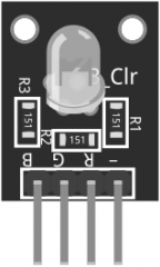
Specifications
Operating Voltage 5V
LED drive mode: Common cathode driver
LED diameter: 5 mm
Board size15mm x 19mm [0.59in x 0.75in]
RGB LED interaction with Arduino
Connect the red pin (R) on the KY-016 to pin 11 on the Arduino. Blue (B) to pin 10, green (G) to pin 9 and ground (-) to GND. Notice that you do not need to use limiting resistors since they are already included on the board.
| RGB LED Module | Arduino |
| R | Pin 11 |
| B | Pin 10 |
| G | Pin 9 |
| – | GND |

Arduino code
int redpin = 11; // select the pin for the red LED
int bluepin =10; // select the pin for the blue LED
int greenpin =9; // select the pin for the green LED
int val;
void setup() {
pinMode(redpin, OUTPUT);
pinMode(bluepin, OUTPUT);
pinMode(greenpin, OUTPUT);
Serial.begin(9600);
}
void loop() {
for(val = 255; val > 0; val–)
{
analogWrite(11, val);
analogWrite(10, 255 – val);
analogWrite(9, 128 – val);
Serial.println(val, DEC);
delay(5);
}
for(val = 0; val < 255; val++)
{
analogWrite(11, val);
analogWrite(10, 255 – val);
analogWrite(9, 128 – val);
Serial.println(val, DEC);
delay(5);
}
}
Result
The following Arduino sketch will gradually increase/decrease the PWM values on the red, green and blue pins causing the LED to cycle through various colors.
14. SMD RGB LED
RGB full color LED Module KY-009 for Arduino, emits a range of colors by mixing red, green, and blue light. The amount of each color is adjusted using PWM.
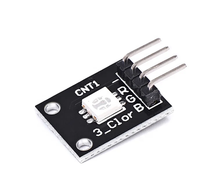
Specifications
Operating Voltage:
5V max
Red 1.8V ~2.4V
Green 2.8V ~ 3.6V
Blue 2.8V ~ 3.6V
Forward Current: 20mA ~ 30mA
Operating Temperature: -25°C to 85°C [-13°F ~ 185°F]
Dimensions: 18.5mm x 15mm [0.728in x 0.591in]
SMD RGB LED interaction with Arduino
You need to use resistors to prevent burnout.
| KY-009 | Breadboard | Arduino |
| R | 180Ω resistor | Pin 9 |
| G | 110Ω resistor | Pin 10 |
| B | 110Ω resistor | Pin 11 |
| – | GND | GND |

Arduino code
int redpin = 11; //select the pin for the red LED
int bluepin =10; // select the pin for the blue LED
int greenpin = 9;// select the pin for the green LED
int val;
void setup() {
pinMode(redpin, OUTPUT);
pinMode(bluepin, OUTPUT);
pinMode(greenpin, OUTPUT);
Serial.begin(9600);
}
void loop()
{
for(val = 255; val > 0; val–)
{
analogWrite(redpin, val); //set PWM value for red
analogWrite(bluepin, 255 – val); //set PWM value for blue
analogWrite(greenpin, 128 – val); //set PWM value for green
Serial.println(val); //print current value
delay(1);
}
for(val = 0; val < 255; val++)
{
analogWrite(redpin, val);
analogWrite(bluepin, 255 – val);
analogWrite(greenpin, 128 – val);
Serial.println(val);
delay(1);
}
}
Result
The above Arduino sketch will cycle through various colors by changing the PWM value on each of the three primary colors.
15. Two-color LED
3mm Two color LED module KY-011 for Arduino, emits red and green light. You can adjust the amount of each color using PWM

Specifications
Operating Voltage: 2.0v ~ 2.5v
Working Current: 10mA
Diameter: 3mm
Package Type: Diffusion
Color: Red and Green
Beam Angle: 150
Wavelength: 571nm + 644nm
Luminosity Intensity (MCD): 20-40; 40-80
Two color LED interaction with Arduino
You can use 330Ω resistors in order to limit the current from the Arduino and prevent burning the LED.
Two color LED Breadboard Arduino
G 330Ω resistor Pin 10
R 330Ω resistor Pin 11
Y GND

Arduino code
int redpin = 11; // pin for red signal
int greenpin = 10; // pin for green signal
int val;
void setup() {
pinMode(redpin, OUTPUT);
pinMode(greenpin, OUTPUT);
}
void loop() {
for(val = 255; val > 0; val–) {
analogWrite(redpin, val); //dim red
analogWrite(greenpin, 255 – val); // brighten green
delay(15);
}
for(val = 0; val < 255; val++) {
analogWrite(redpin, val); //brighten red
analogWrite(greenpin, 255 – val); //dim green
delay(15);
}
}
Results
The following Arduino sketch will gradually alternate between red and green color.
16. Reed Switch
Reed Switch Module for Arduino is a small electrical switch operated by an applied magnetic field, commonly used as proximity sensor.
The module has both digital and analog outputs. A trimmer is used to calibrate the sensitivity of the sensor.

Specifications
Operating Voltage: 3.3V to 5.5V
Dimensions: 1.5cm x 3.6cm [0.6in x 1.4in]
Reed Switch connection with Arduino
Reed Switch Arduino
A0 A0
G GND
+ 5V
D0 3

We’ll read values from both digital and analog interfaces on the Reed switch.
The digital interface will send a HIGH signal when a magnetic field is detected, turning on the LED on the Arduino (pin 13).
Arduino code
int led = 13; // define the LED pin
int digitalPin = 3; // KY-025 digital interface
int analogPin = A0; // KY-025 analog interface
int digitalVal; // digital readings
int analogVal; //analog readings
void setup()
{
pinMode(led, OUTPUT);
pinMode(digitalPin, INPUT);
//pinMode(analogPin, OUTPUT);
Serial.begin(9600);
}
void loop()
{
// Read the digital interface
digitalVal = digitalRead(digitalPin);
if(digitalVal == HIGH) // if magnetic field is detected
{
digitalWrite(led, HIGH); // turn ON Arduino’s LED
}
else
{
digitalWrite(led, LOW); // turn OFF Arduino’s LED
}
// Read the analog interface
analogVal = analogRead(analogPin);
Serial.println(analogVal); // print analog value to serial
delay(100);
}
17. Mini Reed
A reed switch is a magnetic sensor that is normally open and gets closed when exposed to a magnetic field.

Specifications:
Mini Magnetic Reed Switch Module consists of a 10kΩ resistor and a small reed switch actuated by a magnetic field, commonly used in mechanical systems as proximity sensors. It is compatible with Arduino.
Operating Voltage: 3.3V to 5v
Output Type: Digital
Board Size: 18.5mm x 15mm [0.728in x 0.591in]
Connecting with Arduino
Mini Reed Switch Arduino
S 2
middle +5V
– GND