Description
Description :
NFC (near field Communication), also known as the short-range wireless communication, high frequency wireless communication technology is a short range, allowing for no-contact-point of transfer of data between the electronic (in ten centimeters) to the trading data. It was firdt developrd by Sony and Philips for their mobile phones.
NFC is a popular technology in recent years. We often heard this work while smartphone company such as Samsung or HTC introduces their latest high-end phones. Almost all the high-end phone in the market support NFC.
Features:
Small size
It is easy to integrate into your designs support for I2C, SPI, HSU (high speed UART)
You can easily switch between these communications
Work in NFC Mode or RFID reader/writer Mode (can work in the State of near-field communications, RFID
Mifare 1 k, 4 k, ultralight, and DesFire card
ISO / IEC 14443-4 cards, like CD97BX, CD light, Desfire, P5CN072 (SMX)
Innovision Jewel cards, like IRT5001 card
FeliCa cards like RCS_860 and RCS_854
Plug and Play compatible
Council in the antenna, support communication distance 5 cm ~ 7 cm
For level shifter, standard 5 V TTL for I2C and UART, 3.3 V TTL for SPI
How to get with PN532 NFC RFID Reader/Writer Module V3
Near field communication (NFC) is a set of standards for smartphones and similar devices to establish radio communication with each other by touching them together or bringing them into close proximity, usually no more than a few centimeters. This module is built around NXP PN532. NXP PN532 is very popular in NFC area.
Overview
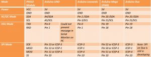
This NFC reader/writer module is red in color and have 12 pin in total for interface with Arduino, One row has 4 pin used to communicate with Arduino in HSU and I2C mode where as the remaining 8 pin are on 90 degrees from the 4 pin side is used to communicate in SPI mode.
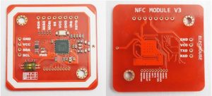
This board has a SMD (Surface Mounted Device) toggle switch on it, which is use to select the working mode and it has one row of 8 pin which is used to communicate is SPI (Serial Peripheral Interface) mode and another row at 90 degrees and has 4 pin which is used in both I2C (Inter-Integrated Circuit) and HSU (High Speeed UART).
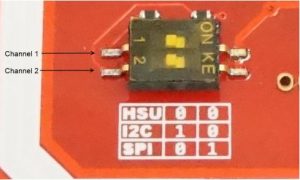
The I2C and HSU shares the same pins. The definition of IIC pins is printed at front and the HSU’s is printed at the back. The HSU mode is configured as the default mode. But you could change the interface by setting the toggle switch.
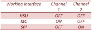
The switch setting is shown as follows:
Pin-out Description
SCK: (Serial Clock Output) used in SPI mode to communicate with Arduino
MISO: (Master Input Slave Output) used in SPI mode as
MOSI: (Master Output Slave Input) used in SPI mode
SS: Slave Selector
VCC: 5 V input pin
GND: Ground pin
IRQ: Interupt Request pin
RSTO: Reset Pin
SDA: (Serial Data Line) used in I2C mode
SCL: (Serial Clock Line) used in I2C mode
This PN532 NFC RFID reader/writer supports the following cards:
- Mifare 1k, 4k, Ultralight, and DesFire cards
- ISO/IEC 14443-4 cards such as CD97BX, CD light, DesFire, P5CN072 (SMX)
- Innovision Jewel cards such as IRT5001 card
- FeliCa cards such as RCS_860 and RCS_854
Interface:
This part of the tutorial is specifically for the breakout board. We show how to use it with SPI. The breakout also supports I2C and HSU but we choose to use in SPI as the most cross-platform method to communicate.
Wiring the Breakout for SPI
The PN532 chip and breakout is designed to be used from 3.3V to 5V in SPI mode, in the I2C mode the voltage is 5V to 25V according to your micro-controller you choose and the voltage it supports. To begin, we’ll solder in the header to the breakout board. You’ll need the 8-pin header piece of header and one 3-pin header piece. Those came in the package you bought or You can break these off of a large piece. Solder the 8-pin header on the 8 holes at the right end of the breakout board.
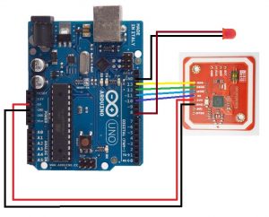
Wire up the PN532 NFC board as follows:
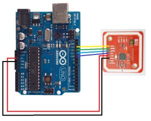
- VCC is connected to the Arduino 5V pin
- GND is connected to the Arduino Ground pin
- SS is connected to the Arduino pin 10
- MOSI is connected to the Arduino pin 11
- MISO is connected to the Arduino pin 12
- SCK is connected to the Arduino pin 13
Also we need to select SPI as the interface mode, so we must select on the Channel 1 the SMD toggle switch should be OFF, the switch on the Channel 2 must be ON (either UP). Please Note without selecting the proper mode in which your NFC module will work into you won’t be able to use your NFC board
Arduino library
The adafruit PN532 library has the ability to read MiFare cards, including the hard-coded ID numbers, as well as authenticate and read/write EEPROM chunks. It can work with both the breakout board using SPI connection.
Library installation
Download the Adafruit PN532 library from github. Uncompress the folder and rename the folder Adafruit_PN532. Install the Adafruit_PN532 library folder by placing it in your adruino sketch folder/libraries folder. You may have to create the libraries subfolder if this is your first library. Restart the arduno IDE. You should now be able to select File> Examples> Adafruit_PN532>readMifare sketch.
Before to upload change these lines as shown below

upload it and open your serial monitor and set the baud rate at 115200 baud.
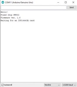
Testing MiFare
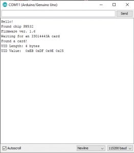
In the serial monitor, you should see that it found the PN532 chip. Then you can place your tag nearby and it will display the 4 byte ID code (this one is 0xEB 0xDF 0x9E 0x25) and then the integer version of all four bytes together. You can use this number to identify each card.
Security system using NFC module
As we done with reading our MiFare classic UID (Unique Identification number) which is unique to every card, we can start a simple security system so that a single user with a matching UID can access a system, here we’re showing a simplified version but you can make it big to 12 user who are allowed to your system.
Parts used:
PN532 NFC reader module V3
LED
Arduino UNO
Solderless BreadBoard
Hardware connection
Connect the NFC reader module as on previous connections and connect te led to pin 8 on arduino board or see the diagram below and make connection. Don’t forget to toggle the switch as show in SPI mode if you don’t the sketch won’y work.
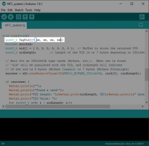
Download this code and edit the following line shown with you 4 number UID and upload to your Arduino.
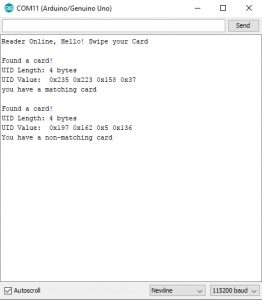
Open your serial monitor with 115200 as the baud rate and swipe your allowed card and see what happens 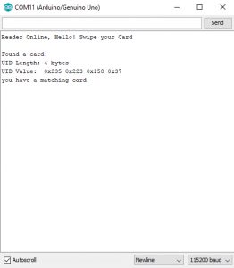
You will get the info of your card and a message that you have a matching card and the LED connected to pin 8 on arduino will light for 5 seconds which is the time set for the user to access the system after the LED will go off. Try another MiFare card and see what happens, the serial monitor will respond that you have got a non-matching card and the LED will remain in its state.
I hope this was a quick introduction yo NFC reader/writer module V3, thanks for reading.
Resourcces:
Arduino Library: Adafruit_PN532 library
Arduino Sketch: