Description
This module is based on the MAX7219 chip which is a compact, serial input common-cathode driver that interfaces microcontrollers to LED matrices. All common microcontrollers can be connected to this module by using a 4-wire serial interface. Each output can be addressed without refreshing the entire display. This module requires only 3 I/O lines for driving the display, making it ideal for your microcontroller projects.
Specification
- Operating Voltage: DC 4.7V~5.3V
- Operating Current: 320mA
- Max Operating Current: 2A
- Operating Temperature: 0~50 Degree
Getting started with the Max7219 dot matrix module
Today we will be focusing on displaying mini graphics and texts on an 8×8 LED matrix using the MAX7219 LED driver and the Arduino Uno.
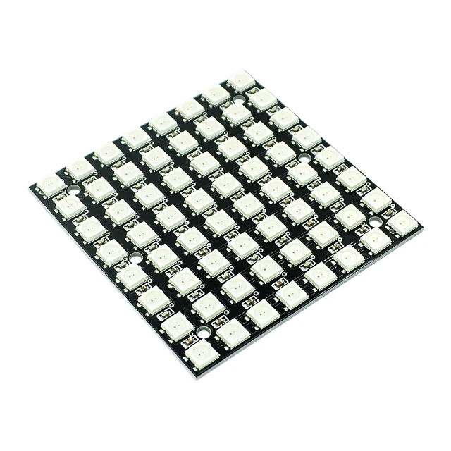
The 8×8 LED matrix displays are usually used for the display of symbols, simple graphics and texts. Made of super bright LEDs, they produce low resolution display and can be daisy chained to produce larger displays.
To enable us to control the display easily, we will be using the MAX7219 LED display driver module. Although this driver comes attached to the LED Matrix display that we will be using for this tutorial, its important to treat them separately, so you can understand how the LED driver works and be able to use it in case you are unable to get an 8×8 LED Matrix display that comes with the LED Driver.
The MAX7219 are compact, serial input/output common-cathode display drivers that interface to microcontrollers and microprocessors to control 7-segment numeric LED displays of up to 8 digits, bar-graph displays, or 64 individual LEDs. Included on the MAX7219 chip is a BCD code-B decoder, a multiplex scan circuitry, a segment and digit drivers, and an 8×8 static RAM that stores each digit. Only one external resistor is required to set the segment current for all LEDs. The MAX7219 also allow the user to select code-B decoding or no-decode for each digit.
Hardware required
- Arduino Uno
- Jumper wires(Male to Female)
- Max7219 dot matrix module
Connecting the Hardware
Connect the Module to the Arduino as shown below
Cs==D11
CLK==D10
DIN==12
GND==GND
VCC==5V

CREATING GRAPHICS FOR DISPLAY ON THE LED MATRIX
![]()
Before we proceed to writing the code for this project, I would like to show you an easy way of creating the graphics to be displayed on the LED Matrix and generating the byte array that will be used in the code to represent the graphics to be displayed. To do this, we will use a very lightweight software which I found online, called “PixeltoMatrix”.
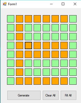
This software allows you draw your graphics by highlighting boxes like some dots connecting sort of game, then generates the byte array which you can then copy and use in your code.
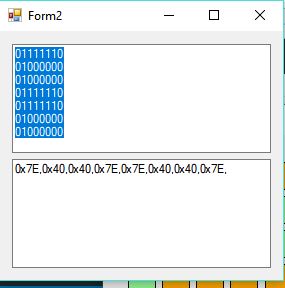
pretty cool right? I thought so too.
Setting up the library
To ensure ease of the coding process, we will use the LEDcontrol library which can be downloaded from here. This Library makes the process of programming the Arduino to drive the LED matrix easy. So as usual, download the library, extract it and copy to your Arduino libraries folder, then start the Arduino IDE.
Upload the sample sketch
#include <LedControl.h>

int DIN = 12;
int CS = 11;
int CLK = 10;

byte e[8]= {0x7C,0x7C,0x60,0x7C,0x7C,0x60,0x7C,0x7C};
byte d[8]= {0x78,0x7C,0x66,0x66,0x66,0x66,0x7C,0x78};
byte u[8]= {0x66,0x66,0x66,0x66,0x66,0x66,0x7E,0x7E};
byte c[8]= {0x7E,0x7E,0x60,0x60,0x60,0x60,0x7E,0x7E};
byte eight[8]= {0x7E,0x7E,0x66,0x7E,0x7E,0x66,0x7E,0x7E};
byte s[8]= {0x7E,0x7C,0x60,0x7C,0x3E,0x06,0x3E,0x7E};
byte dot[8]= {0x00,0x00,0x00,0x00,0x00,0x00,0x18,0x18};
byte o[8]= {0x7E,0x7E,0x66,0x66,0x66,0x66,0x7E,0x7E};
byte m[8]= {0xE7,0xFF,0xFF,0xDB,0xDB,0xDB,0xC3,0xC3};

LedControl lc=LedControl(DIN,CLK,CS,0);

void setup(){
lc.shutdown(0,false); //The MAX72XX is in power-saving mode on startup
lc.setIntensity(0,15); // Set the brightness to maximum value
lc.clearDisplay(0); // and clear the display
}

void loop(){
byte smile[8]= {0x3C,0x42,0xA5,0x81,0xA5,0x99,0x42,0x3C};
byte neutral[8]= {0x3C,0x42,0xA5,0x81,0xBD,0x81,0x42,0x3C};
byte frown[8]= {0x3C,0x42,0xA5,0x81,0x99,0xA5,0x42,0x3C};

printByte(smile);

delay(1000);

printByte(neutral);

delay(1000);

printByte(frown);

delay(1000);

printEduc8s();

lc.clearDisplay(0);

delay(1000);
}

void printEduc8s(){
printByte(e);
delay(1000);
printByte(d);
delay(1000);
printByte(u);
delay(1000);
printByte(c);
delay(1000);
printByte(eight);
delay(1000);
printByte(s);
delay(1000);
printByte(dot);
delay(1000);
printByte(c);
delay(1000);
printByte(o);
delay(1000);
printByte(m);
delay(1000);
}

void printByte(byte character []){
int i = 0;
for(i=0;i<8;i++)
{
lc.setRow(0,i,character[i]);
}
}
Result

Package includes:
1×Max7219 dot matrix module