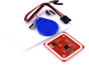
Description
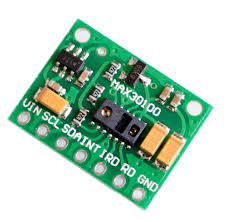
Heart Rate click carries Maxim’s MAX30100 integrated pulse oximetry and heart-rate sensor. Developers of end-user applications should note that the readings can be negatively impacted by excess motion and changes in temperature. Also, too much pressure can constrict capillary blood flow and therefore diminish the reliability of the data. A programmable INT pin is also available to use.
Specification:
- 3.3V power supply.
- Optical sensor: IR and red LED combined with photodetector
- Measures absorbance of pulsing blood
- I2C interface plus INT pin
- 3.3V power supply
Getting started with the MAX30100 Pulse Oximeter Heart Rate Sensor Development Board
In this project we will be Interfacing MAX30100 Pulse Oximeter Sensor with Arduino that can measure Blood Oxygen & Heart Rate and display it on serial monitor. The blood Oxygen Concentration termed as SpO2 is measured in Percentage and Heart Beat/Pulse Rate is measured in BPM. The MAX30100 is a Pulse Oximetry and heart rate monitor sensor solution.
Step1: Hardware required
- Arduino UNO
- MAX30100 Pulse Oximeter Heart Rate Sensor
- Jumper wires
- Resistor 4.7k ohm x3
How does Pulse Oximeter Works?
Oxygen enters the lungs and then is passed on into blood. The blood carries oxygen to the various organs in our body. The main way oxygen is carried in our blood is by means of hemoglobin. During a pulse oximetry reading, a small clamp-like device is placed on a finger, earlobe, or toe.

Small beams of light pass through the blood in the finger, measuring the amount of oxygen. It does this by measuring changes in light absorption in oxygenated or deoxygenated blood.

Working of MAX30100 Pulse Oximeter and Heart-Rate Sensor
The device has two LEDs, one emitting red light, another emitting infrared light. For pulse rate, only the infrared light is needed. Both the red light and infrared light is used to measure oxygen levels in the blood.
When the heart pumps blood, there is an increase in oxygenated blood as a result of having more blood. As the heart relaxes, the volume of oxygenated blood also decreases. By knowing the time between the increase and decrease of oxygenated blood, the pulse rate is determined.
It turns out, oxygenated blood absorbs more infrared light and passes more red light while deoxygenated blood absorbs red light and passes more infrared light. This is the main function of the MAX30100: it reads the absorption levels for both light sources and stored them in a buffer that can be read via I2C.
Interfacing MAX30100 Pulse Oximeter Sensor with Arduino
Now let us interface MAX30100 Pulse Oximeter Sensor with Arduino and display the value in serial monitor. So the circuit diagram and connection is given below. connect the INT, SDA, SCL pin to the external 4.7K Pull up resistor as shown in the image below. You can follow the same.

Just follow this wiring setup
| Purple MAX30100 Module | Arduino UNO/Nano |
| VIN | 5V |
| GND | GND |
| SCL | A5 |
| SDA | A4 |
| INT | D2 |
Step3: Setting up the library
so before reading the MAX30100 Pulse Oximeter Heart Rate Sensor we must have the library, so you can download it here . install the library by extracting that zipped file in the library folder as shown below .

Step4: Upload the sample sketch
here’s an example sketch:
#include <Wire.h>
#include “MAX30100_PulseOximeter.h”
#define REPORTING_PERIOD_MS 1000
// PulseOximeter is the higher level interface to the sensor
// it offers:
// * beat detection reporting
// * heart rate calculation
// * SpO2 (oxidation level) calculation
PulseOximeter pox;
uint32_t tsLastReport = 0;
// Callback (registered below) fired when a pulse is detected
void onBeatDetected()
{
Serial.println(“Beat!”);
}
void setup()
{
Serial.begin(115200);
Serial.print(“Initializing pulse oximeter..”);
// Initialize the PulseOximeter instance
// Failures are generally due to an improper I2C wiring, missing power supply
// or wrong target chip
if (!pox.begin()) {
Serial.println(“FAILED”);
for(;;);
} else {
Serial.println(“SUCCESS”);
}
// The default current for the IR LED is 50mA and it could be changed
// by uncommenting the following line. Check MAX30100_Registers.h for all the
// available options.
// pox.setIRLedCurrent(MAX30100_LED_CURR_7_6MA);
// Register a callback for the beat detection
pox.setOnBeatDetectedCallback(onBeatDetected);
}
void loop()
{
// Make sure to call update as fast as possible
pox.update();
// Asynchronously dump heart rate and oxidation levels to the serial
// For both, a value of 0 means “invalid”
if (millis() – tsLastReport > REPORTING_PERIOD_MS) {
Serial.print(“Heart rate:”);
Serial.print(pox.getHeartRate());
Serial.print(“bpm / SpO2:”);
Serial.print(pox.getSpO2());
Serial.println(“%”);
tsLastReport = millis();
}
}
Step5: Testing the circuit
open your serial monitor by clicking on the icon in the right top corner(like search icon).If you followed the wiring diagram and uploaded this sketch to your Arduino, the red LED on the board should light up and you will see this on the serial monitor:


