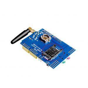
Description
The GPRS Shield is based on SIM900 module from SIMCOM and compatible with Arduino and its clones. The GPRS Shield provides you a way to communicate using the GSM cell phone network. The shield allows you to achieve SMS, MMS, GPRS and Audio via UART by sending AT commands (GSM 07.07 ,07.05 and SIMCOM enhanced AT Commands). The shield also has the 12 GPIOs, 2 PWMs and an ADC of the SIM900 module
Features:
- Quad-Band 850 / 900/ 1800 / 1900 MHz – would work on GSM networks in all countries across the world.
- GPRS multi-slot class 10/8
- GPRS mobile station class B
- Compliant to GSM phase 2/2+
- Class 4 (2 W at 850 / 900 MHz)
- Class 1 (1 W at 1800 / 1900MHz)
- Control via AT commands : Standard Commands: GSM 07.07 and 07.05 – Enhanced Commands: SIMCOM AT Commands.
- Short Message Service : so that you can send small amounts of data over the network (ASCII or raw hexadecimal).
- Embedded TCP/UDP stack : allows you to upload data to a web server.
- RTC supported.
- Selectable serial port.
- Speaker and Headphone jacks
- Low power consumption : 1.5mA(sleep mode)
- Industrial Temperature Range – -40°C to +85 °C
Application:
- M2M (Machine 2 Machine) Applications.
- Remote control of appliances.
- Remote Weather station or a Wireless Sensor Network.
- Vehicle Tracking System with a GPS module.
Cautions:
- Make sure your SIM card is unlocked.
- The factory default setting for the GPRS Shield UART is 19200 bps 8-N-1. (Can be changed using AT commands).
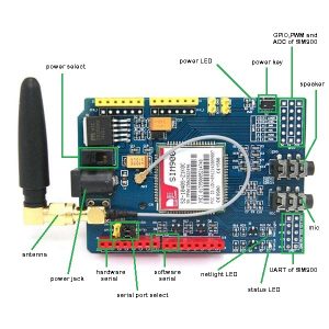
- Power select : select the power supply for GPRS shield(external power or 5v of arduino)
- Power jack * connected to external 4.8~5VDC power supply
- Antenna interface : connected to external antenna
- Serial port select * select either software serial port or hardware serial port to be connected to GPRS Shield
- Hardware Serial : D0/D1 of Arduino
- Software serial – D7/D8 of Arduino
- Status LED – tell whether the power of SIM900 is on
- Net light – tell the status about SIM900 linking to the net
- UART of SIM900 – UART pins breakout of SIM900
- Microphone : to answer the phone call
- Speaker : to answer the phone call
- GPIO,PWM and ADC of SIM900 – GPIO,PWM and ADC pins breakout of SIM900
- Power key : power up and down for SIM
HOW TO GET STARTED WITH SIM900
The module power up for DC supply of 2A from 5V to 12V. On the back it has a simslot on which you insert a unlocked sim. It has a a master power select and a power key for turning it on/off. When it is receiving enough power the power LED on board must light then you must press the power key for about 2 seconds until LEDs of STATUS and NETLIGHT blink. wait for a half-minutes and see if the NETLIGHT LED blinks once every 3 seconds, hence your simcard is connected onto a network, there are also microphone and speaker jack.The GSM module ground is found on UART of SIM900.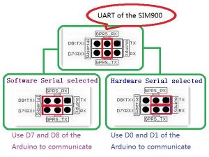
You can either choose to work with hardware serial or software serial using serial port selector. .once you choose software serial pin D7 -> Rx D8 -> Tx while for hardware selectoryou can use Rx and TX found on UART of SIM900. Arduino communication between GSM sim900 and arduino is serial.
There are two ways to chose to work with this module.
1st way: you must connect arduino (Rx and Tx) pin for communication.You may connect GSM Tx-> Arduino Rx and GSM Rx -> Arduino Tx. Connect also the GSM ground pin to Arduino ground pin.
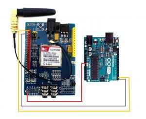
2nd way:by use of SoftwareSerial Library you can select two PWM enabled pins of arduino and use them as Tx and Rx. When coding also I also used this. Where pin D9 and D10 on arduino act as TX and RX respectively.
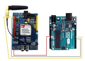
NOTE:The 1st way is a little bit more complicated because when you will need to upload a new program onto your arduino you must disconnect the GSM module pins and upload it to your arduino. So stick up with the 2nd way.
Once the connections are made, it’s time for coding in arduino. Mainly GSM module use AT commands that can be found on internet, but by the use of arduino we can use user friendly code as you wish an example
AT-command for text is “AT+CMGF=1” but we can assign this characters into “text”and we type the message to be sent by the GSM only using “text” to invoke the text mode for GSM.
there are functions used in GSM library for GSM module an example of them are:
- SendMessage() :used to send message
- ReceiveMessage(): used to receive message
- GetVoicecCallStatus(): used for get the state when it is called etc
here is the codes: send & receive SMS
NOTE: not all arduino support software serial on D7 and D8 for more information please visit http://arduino.cc/en/Reference/SoftwareSerial
Ressources:
Documents:
Arduino sketches: