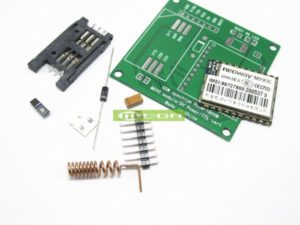
Description
This is WiFi serial transceiver module, based on ESP8266 SoC. The SOC has Integrated TCP/IP protocol stack, ESP8266 is a highly integrated chip designed for the needs of a new connected world. It offers a complete and self-contained Wi-Fi networking solution, allowing it to either host the application or to offload all Wi-Fi networking functions from another application processor.
Specification
- 1M Flash
- 802.11 b/g/n
- Wi-Fi Direct (P2P), soft-AP
- Integrated TCP/IP protocol stack
- Integrated TR switch, balun, LNA, power amplifier and matching network
- Integrated PLLs, regulators, DCXO and power management units
- +19.5dBm output power in 802.11b mode
- Power down leakage current of<10uA
- Integrated low power 32-bit CPU could be used as application processor
- SDIO 1.1/2.0, SPI, UART
- STBC, 1×1 MIMO, 2×1 MIMO
- A-MPDU & A-MSDU aggregation & 0.4ms guard interval
- Wake up and transmit packets in < 2ms
- Standby power consumption of < 1.0mW (DTIM3)
GETTING STARTED WITH THE ESP8266 ESP-01
The ESP8266 ESP-01 is a Wi-Fi module that allows microcontrollers access to a Wi-Fi network. This module is a self-contained SOC (System On a Chip) that doesn’t necessarily need a microcontroller to manipulate inputs and outputs as you would normally do with an Arduino, for example, because the ESP-01 acts as a small computer. Depending on the version of the ESP8266, it is possible to have up to 9 GPIOs (General Purpose Input Output). Thus, we can give a microcontroller internet access like the Wi-Fi shield does to the Arduino, or we can simply program the ESP8266 to not only have access to a Wi-Fi network, but to act as a microcontroller as well. This makes the ESP8266 very versatile, and it can save you some money and space in your projects.
In this tutorial we are going to show you how to set up the ESP-01 Wi-Fi module, configure it, and verify that there is communication established between the module and another device.
Step 1: Materials
These are the components that you will need:
Step 2: ESP-01 Setup
When you buy the ESP8266 ESP-01, it comes with a pre-installed AT firmware. It is possible to program the chip with another firmware such as NodeMCU, for example. However, AT firmware is compatible with the Arduino IDE, so we are going to use this firmware for this tutorial


Connect the ESP-01 as shown on the above pictures after the connections
Upload the BareMinimum(File>examples>basics>bareminimum) example to ensure that no previous programs are running and using the serial communication channel. Next, open the serial monitor and type the following command:
AT
You should get an “OK” response. This means that the module is working and that you are good to go. Now we are ready to test a two way communication between the module and another device. for those who didn’t receive any response follow these steps to enable your ESP-01
(assuming Windows), using the Control Panel on your computer, go into the device manager and make sure the port for the Arduino shows up when you power the Arduino from the USB port.
A new entry should pop up after a few seconds. That is the port number for your Arduino. Go into the Properties in port setting tab and make sure it is set to 115200 baud.
Now in the Arduino Interface, make sure the Baud rate and ports match what you saw in the Device Manager in Windows. If they do, open the Serial Monitor and make sure at the bottom you have it set to 115200 baud and that Both NL and CR is selected in the first drop down box.
Now at the top in the input box, enter capital AT and click send. If you do not receive OK you either accidentally flashed your ESP8266 and over wrote the factory firmware, your serial connection is bad (change USB cables and try again), or you received an ESP8266 that did not come with the AT firmware or is defective. In which case you should try a different one.
Step 4: Basic AT Commands
The ESP8266 ESP-01 module has three operation modes:
- Access Point (AP)
- Station (STA)
- Both
In AP the Wi-Fi module acts as a Wi-Fi network, or access point (hence the name), allowing other devices to connect to it. This does not mean that you will be able to check your Facebook from your device while the ESP-01 module is operating in the AP mode. It simply establishes a two way communication between the ESP8266 and the device that is connected to it via Wi-Fi.
In STA mode, the ESP-01 can connect to an AP such as the Wi-Fi network from your house. This allows any device connected to that network to communicate with the module.
The third mode of operation permits the module to act as both an AP and a STA.
Step 5: Basic AT Commands – STA Mode
In this tutorial, we are going to set the module to operate in STA mode by typing the following command:
AT+CWMODE=1
After sending this command you must receive “OK” response, The corresponding number for each mode of operation is as follows:
- STA = 1
- AP = 2
- Both = 3
Step 6: Basic AT Commands – Check Mode
If you want to check what mode your Wi-Fi module is in, you can simply type the following command:
AT+CWMODE?
This will display a number (1, 2, or 3) associated with the corresponding mode of operation.
Step 7: Basic AT Commands – Connecting Wi-Fi Network
Once we have the ESP-01 operating in STA mode, we need to connect to a Wi-Fi network. First we can check if we are already connected to one by sending the command:
AT+CIFSR
This will display the station IP address of our ESP-01 module. If you don’t get an IP address after entering the previous command, use the following command to connect to your network:
AT+CWJAP= “Wi-FiNetwork”,“Password”
Type the name of your Wi-Fi network and the password to connect to it. Make sure you include the quotation marks. After a couple of seconds, you should get an “OK” response. You can check again to see if you have an IP address using the AT+CIFSR command.
Step 8: Basic AT Commands – Enable Connections
Then we need to enable multiple connections before we can configure the ESP8266 ESP-01 module as a server. Type the next command:
AT+CIPMUX=1
Once again, each number is associated with a type of connection:
- Single = 0
- Multiple = 1
The following step is to start the server at port 80:
AT+CIPSERVER=1,80
The first number is used to indicate whether we want to close server mode (0), or open server mode (1). The second number indicates the port that the client uses to connect to a server. We chose port 80 because this is the default port for HTTP protocol.
Step 9: Basic at Commands – Response

Now, when we open a web browser and type the IP address of our ESP module we get the following response as shown in the image above.
This is the HTTP request that our computer sends to the server to fetch a file. It contains some interesting information such as what file you want to retrieve, name of the browser and version, what operating system you are using, what language you prefer to receive the file in, and more.
Step 10: Basic AT Commands – Send and Display Data

We can now use the following commands to send some data and display it in our web browser’s window:
AT+CIPSEND=0,5
The “0” indicates the channel through which the data is going to be transferred; while “5” represents the number of characters that are going to be sent.
When we hit enter, the symbol “>” appears. This indicates that we can now type the characters that we want to send to the browser. In this example we chose “hello.”
After a couple of seconds we get the response “SEND OK.” This means that the data has been transmitted successfully to the client. However, nothing appears on the web browser’s window yet. This is because it is required to close the channel first in order to display the characters. We use the following command to close the channel:
AT+CIPCLOSE=0
“0” indicates the channel that is being closed.
Once we hit enter, our message is displayed on the web browser’s window as shown in the image above.