Description
RDM6300 125Khz RFID Card Read Module is designed for reading code from 125KHz card compatible read-only tags and read/write card . It can be applied in office/home security, personal identification, access control, anti-forgery, interactive toy and production control systems etc.
The device is a very popular RFID card read module for arduino users, it can read 125K EM4100 series RFID card. This module is easy to use, serial port connect to arduino MCU after power up, when RFID car enter into card reading range, this module will send the card number to arduino by UART.
Features:
- Support external antenna
- Maximum effective distance up to 50mm
- Less than 100ms decoding time
- UART TTL interface
- Support EM4100 compatible read only or read/write tags
- Built-in external bi-color LED and buzzer driver
- Small outline design
How to get started with EM4100 125KHz card reader module
Learn how to use RFID readers with your Arduino. In this instalment we use an EM4100 RFID reader module.
Introduction
RFID stands for Radio Frequency IDentification. Some of us have already used these things, and they have become part of everyday life. For example, with electronic vehicle tolling, door access control, public transport fare systems and so on. It sounds complex – but isn’t.
To explain RFID for a person, we can use a key and lock analogy. Instead of the key having a unique pattern, RFID keys hold a series of unique numbers which are read by the lock. It is up to our Arduino sketch to determine what happens when the number is read by the lock. The key is the tag, card or other small device we carry around or have in our vehicles. We will be using a passive key, which is an integrated circuit and a small aerial antenna. This uses power from a magnetic field associated with the lock.
Overview
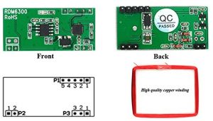
Unlike other module, this EM4100 RFID 125kHZ card reader module don’t have on board pin marking on it but because it is simple. just look at the front view and group your pin according to the above image.
Pin-Description
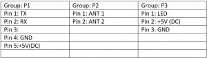
TX : Transmitter pin
RX : Receiver pin
GND: Ground from power supply
VCC : Power supply pin 5v DC current
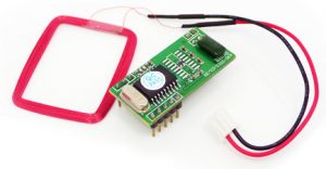
In this tutorial we’ll be using 125 kHz tags. To continue with the analogy our lock is a small circuit board and a loop aerial. This has the capability to read the data on the IC of our key, and some locks can even write data to keys. Our reader (lock) example is show in the image above.
These readers are quite small and inexpensive – however the catch is that the loop aerial is somewhat fragile. So be gentle when using your EM4100 card reader module.
Setting up the RFID reader
This is a short exercise to check the reader works and communicates with the Arduino. You will need:
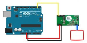
Simply insert the RFID reader main board into a solderless breadboard. Then use jumper wires to connect the second and third pins at the top-left of the RFID board to Arduino 5V and GND respectively. The RFID coil connects to the two pins on the top-right (they can go either way). Finally, connect a jumper wire from the bottom-left pin of the RFID board to Arduino digital pin 2 as shown above.
Your First Arduino Sketch
Next, upload the following sketch to your Arduino and open the serial monitor window in the IDE. If you’re wondering why we used SoftwareSerial – if you connect the data line from the RFID board to the Arduino’s RX pin – you need to remove it when updating sketches, so this is more convenient. Now start waving RFID cards or tags over the coil. You will find that they need to be parallel over the coil, and not too far away.
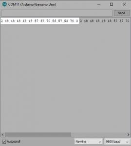
The reader returns the card’s unique ID number which starts with a 2 and ends with a 3. While you have the sketch operating, read the numbers from your RFID tags and note them down, you will need them for future sketches.
Reading and Recognising RFID Cards
To do anything with the card data, we need to create some functions to retrieve the card number when it is read and place in an array for comparison against existing card data (e.g. a list of accepted cards) so your systems will know who to accept and who to deny. Using those functions, you can then make your own access system, time-logging device and so on.
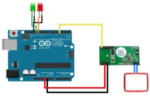
Let’s demonstrate an example of this. It will check if a card presented to the reader is on an “accepted” list, and if so light a green LED, otherwise light a red LED. Use the hardware from the previous sketch, but add a typical green and red LED with 560 ohm resistor to digital pins 13 and 12 respectively. Then upload the following sketch.
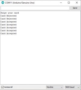
In the sketch we have a few functions that take care of reading and comparing RFID tags. Notice that the allowed tag numbers are listed at the top of the sketch, you can always add your own and more – as long as you add them to the list in the function checkmytags() which determines if the card being read is allowed or to be denied. The function readTags() takes care of the actual reading of the tags/cards, by placing the currently-read tag number into an array which is them used in the comparison function checkmytags(). Then the LEDs are illuminated depending on the status of the tag at the reader. Open your serial monitor and bring any 125kHZ card near the aerial, the following would happen: if it is the allowed card the serial monitor will print the card accepted and the green LED connected on pin 13 will illuminate. When you bring a non-registered card, the serial monitor will print that the card is rejected and the red LED will illuminate.
Ressources:
Arduino sketch