Description
HC-05 module is an easy to use Bluetooth SPP (Serial Port Protocol) module, designed for transparent wireless serial connection setup.
Serial port Bluetooth module is fully qualified Bluetooth V2.0+EDR (Enhanced Data Rate) 3Mbps Modulation with complete 2.4GHz radio transceiver and baseband. It uses CSR Bluecore 04-External single chip Bluetooth system with CMOS technology and with AFH(Adaptive Frequency Hopping Feature).
Specifications:
- Hardware Features
- Typical -80dBm sensitivity
- Up to +4dBm RF transmit power
- Low Power 1.8V Operation ,1.8 to 3.6V I/O
- PIO control
- UART interface with programmable baud rate
- With integrated antenna
- With edge connector
Software Features:
- Default Baud rate: 38400, Data bits: 8, Stop bit: 1, Parity: No parity, Data control: has.
- Supported baud rate: 9600, 19200, 38400, 57600, 115200, 230400, 460800.
- Given a rising pulse in PIO0, device will be disconnected.
- Status instruction port PIO1: low-disconnected, high-connected;
- PIO10 and PIO11 can be connected to red and blue led separately. When master and slave are paired, red and blue led blinks 1time/2s in interval, while disconnected only blue led blinks 2times/s.
- Auto-connect to the last device on power as default.
- Permit pairing device to connect as default.
- Auto-pairing PINCODE:”0000” as default
- Auto-reconnect in 30 min when disconnected as a result of beyond the range of connection.
How to get satrted with HC-05zs-040 Bluetooth module
HC-05 module is an easy to use Bluetooth SPP (Serial Port Protocol) module,designed for transparent wireless serial connection setup. The HC-05 Bluetooth Module can be used in a Master or Slave configuration, making it a great solution for wireless communication.This serial port bluetooth module is fully qualified Bluetooth V2.0+EDR (Enhanced Data Rate) 3Mbps Modulation with complete 2.4GHz radio transceiver and baseband. It uses CSR Bluecore 04-External single chip Rluetooth system with CMOS technology and with AFH (Adaptive Frequency Hopping Feature).
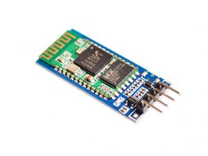
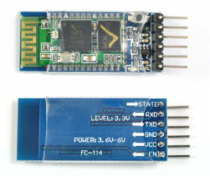 Bluetooth Module HC-05 Zs-040
The Bluetooth module HC-05 is a MASTER/SLAVE module. By default the factory setting is SLAVE.The Role of the module (Master or Slave) can be configured only by AT COMMANDS.The slave modules cannot initiate a connection to another Bluetooth device, but can accept connections. Master module can initiate a connection to other devices.The user can use it simply for a serial port replacement to establish connection between MCU and GPS, PC to your embedded project, etc.Just go through the datasheet for more details
Hardware Features
- Typical sensitivity:-80dBm
- RF transmit power: Up to +4dBm.
- Input Voltage: 3.3 to 5 V I/O.
- UART interface with programmable baud rate.
- With integrated antenna.
- With edge connector.
Software Features
- Slave default Baud rate: 9600, Data bits:8, Stop bit:1,Parity:No parity.
- Auto-connect to the last device on power as default.
- Permit pairing device to connect as default.
- Auto-pairing PINCODE:”1234” as default.
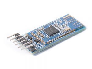
Pin Description
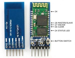 The HC-05 Bluetooth Module has 6 pins. They are as follows:
- ENABLE: When enable is pulled LOW, the module is disabled which means the module will not turn on and it fails to communicate.When enable is left open or connected to 3.3V, the module is enabled i.e the module remains on and communication also takes place.
- Vcc: Supply Voltage 3.3V to 5V
- GND: Ground pin
- TXD & RXD: These two pins acts as an UART interface for communication
- STATE: It acts as a status indicator. When the module is not connected to / paired with any other bluetooth device, signal goes Low. At this low state, the led flashes continuously which denotes that the module is not paired with other device. When this module is connected to/paired with any other bluetooth device, the signal goes High. At this high state, the led blinks with a constant delay say for example 2s delay which indicates that the module is paired.
BUTTON SWITCH: This is used to switch the module into AT command mode. To enable AT command mode, press the button switch for a second. With the help of AT commands, the user can change the parameters of this module but only when the module is not paired with any other BT device. If the module is connected to any other bluetooth device, it starts to communicate with that device and fails to work in AT command mode.
INTERFACE AND EXAMPLE CODE
The HC-05 bluetooth module can’t do anything by itself; it needs to be connected to a microcontroller such as arduino. At this time you don’t need too many libraries to download, we will only use Softwareserial library that is included in newer version from arduino IDE 1.0.2
Required Materials
In this tutorial we’ll show you how to get two modules talking to each other, but keep in mind that you can use more than two modules in your projects. Through the master bluetooth module one arduino will send command to turn on an LED connected to another arduino which will receive data through a slave bluetooth module.
Here’s is what you’ll need:
- 2×HC-05 bluetooth modules (here we used two HC-05 but also HC-06 can work also)
- 2×Arduino Board
- 2×1k Resistors
- 2×2k Resistors
- Jump wires
- Solderless breadboard
Before blinking the LED on the slave arduino, first we must tweak somethings through this process
- AT-Mode: sending AT command to our modules so we can use them as all bluetooth devices.
- Pair, Bin, Link: pairing bluetooth modules so that they can communicate each other.
- Arduino to Arduino Communication
So let’s get started with:
1. AT-MODE
AT mode allows you to interrogate the BT module and to change some of the settings; things like the name, the baud rate, whether or not it operates in slave mode or master mode. When used as a master device AT commands allow you to connect to other Bluetooth slave devices. To activate AT mode on the HC-05 zs-040 modules we can:
- Hold the small button switch closed while powering on the module.
- Set pin 34 HIGH (3.3v) when power on.
- Close the small push button switch after the HC-05 is powered.
- Pull pin 34 HIGH after powering the HC-05.
Enters AT mode with the built in AT mode baud rate of 38400. The baud rate cannot be changed by the user. If you keep pin 34 HIGH you will enable the “full” AT mode which allows all AT commands to be used. If you let pin 34 return LOW after power on then “mini” AT mode will be enabled.
Here’s how to do it: connect the bluetooth module as on the schematics and upload this Arduino sketch(no.1):
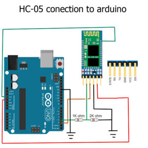
HC-05 with pin 34 connected by a probe clip. You can also simply hold a piece of jump wire to the pin. For a long term solution you would need to solder a wire to pin 34. I use software serial on Arduino pins 2 and 3 to talk to the HC-05. This means I can still use the hardware serial to talk to the serial monitor on a host computer.
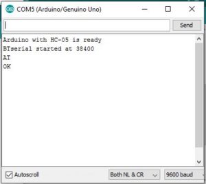
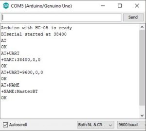
Now as your bluetooth is connected to your PC upload the above code in the Arduino IDE 1.8.1 (I’m using this one to control the Master bluetooth module). hence open your serial monitor wiht the correct baud rate (9600).
The HC-05 expects commands to include a carriage return and newline characters (rn). You can add these automatically in the serial monitor by selecting Both NL & CR at the bottom of the window.

You can also enter them manually in the form ATrn. If you forget to add carriage return and newline characters the HC-05 will not respond.
Example commands
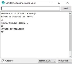
AT – simple feedback request. Will return
OK
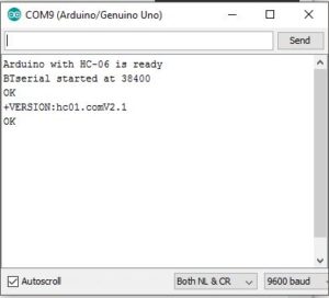
AT+VERSION – returns the firmware version. In my case it returns
+VERSION: hc01.comV2.1
OK
AT+STATE – returns the current state of the module
+STATE:INITIALIZED
OK
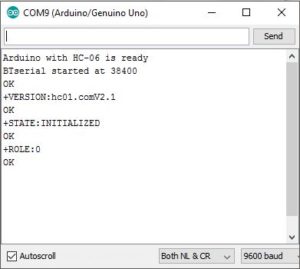
AT+ROLE – the possible values are ; 0 – Slave, 1 – Master, 2 – Slave-Loop
Returns
+ROLE:0
OK
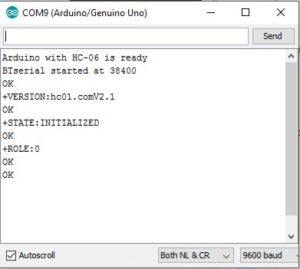
To change to Master Mode, enter AT+ROLE=1, returns:
OK
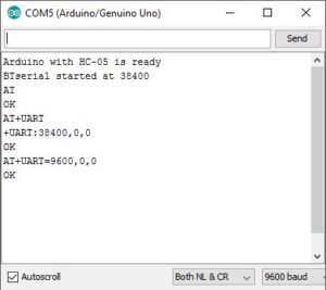
AT+UART – returns the baud rate used by the HC-05 in communication mode. The default for the modules I have is 38400.
Returns:
+UART:38400,0,0
OK
To change the baud rate to 9600 – AT+UART=9600,0,0
Returns:
OK
Windows does not support baud rates above 115200. If you accidentally set the baud rate higher than 115200 you will not be able to use communication mode.You should still be able to enter AT mode at 38400 and change the communication mode baud rate to something Windows can handle.
AT+NAME
Querying the modules name with AT+NAME? only works in “full” At mode. If you cannot get AT+NAME? to work you need to bring pin 34 HIGH.Changing the modules name with AT+NAME=newname works in “full” AT mode and “mini” AT mode.
What you should get is:
AT+NAME, returns
+NAME: MasterBT
OK
Other commands that require pin 34 to be HIGH are AT+INQ and AT+RNAME. This is not a complete list through.
Full list of AT commands

This list is taken from the EGBT-045MS bluetooth module user guide and not all commands may be supported or work straight away. For example AT+NAME? only works when pin 34 is HIGH.For more information look at the HC-05 user guide or the EGBT-046S/EGBT-045MS user guide.
2. PAIR, BIND, LINK
How to set up the HC-05 to always connect to the same HC-05. For this we use PAIR, BIND, and LINK. I am using 2 separate Arduino IDEs; version 1.8.1 which is installed, and version 1.6.3 which I run from a folder (it is the non install version). This allows me to use 2 IDEs at the same time, each connected to a different Arduino. It also gives me 2 serial monitors, one for each Arduino.
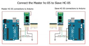
Still I’m using two HC-05 zs040 bluetooth module The HC-05 has 2 AT modes which I refer to as “mini” AT mode and “full” AT mode and some commands only work when in “full” AT mode. To enter “full” AT mode pin 34 needs to be HIGH and kept HIGH. To accomplish this I have made a connection from pin 34 to +3.3v. See the diagram below
HC-05 Set Up (MasterBT)
Setup your Master bluetooth circuit according to this schematics:
I have the HC-05 set with the following values:
- ROLE = 0 (slave mode)
- UART = 9600 (baud rate for communication mode)
- CMODE = 0 (only connect to paired devices)
- PSWD = 1234 (password/PIN for pairing)
I have 2 Arduinos. One connected to a HC-05 zs-040 and one connected to a HC-05 zs-040, both HC-05 have a connection from pin 34 to +3.3v. This activates “full” AT mode. In AT mode I will be using a baud rate of 38400.bBuild the circuit, power on and load the following sketch(no.2).
Because pin 34 on the Bluetooth module is brought HIGH, the HC-05 should enter AT mode on power on.Open the serial monitor on the host computer and confirm you are in AT mode by typing “AT” (no quotes). You should get a reply of “OK” Remember that the HC-05 requires “Both NL & CR” to be set. The sketch echos the commands you enter back to the serial monitor. This makes it a bit easier to follow.
Picture
HC-05 Set Up (SlaveBT)
Build the Slave HC-05 circuit, power on and load the following sketch(no.3). Our HC-05 is set to use 38400 baud rate. if yours is using a different speed the you will need to change the sketch. change the following lines:
BTserial.begin(38400);
Serial.println("BTserial started at 38400");
Change the 38400 to what ever speed your bluetooth module is using.
HC-06 modules start in AT mode so we can start entering commands as soon as we open the serial monitor. Remember that the HC-05 requires commands to be upper case and does not want new lines or carriage returns so set “No line endings” at the bottom of the serial monitor window. Open the serial monitor on the host computer and confirm you are in AT mode by typing “AT” (no quotes). You should get a reply of “OK”.
We don’t need to do few things to prepare the HC-05 Slave. Just make sure the password is the same as the HC-05. The default password for both is 1234 and we don’t need to change it. just put in these few commands. On the slave bluetooth’s serial monitor. Type in the following AT commands to setup the slave bluetooth module. The serial monitor will just send an “OK” as the response for the accepted commands.
AT+RESET
AT+CMODE=0
AT+INIT
AT+INQ
PAIRING AND BINDING
At this point we should have the HC-05 Slave waiting for a connectio, the password/PIN is 1234
The steps to connect to theHC-05 slave are:
- set the same baud rate onboth devices
- make sure the passwords on the HC-05 Master and the HC-05 Slave are the same
- find the address of the HC-05 slave
- pair the HC-05 Master with the HC-05 Slave
- bind the HC-05 Master with the HC-05 Slave
- set the HC-05 Master to only connect with paired devices
- link to the HC-05
1. Set the same baud rate on both devices.
Set the communication mode baud rate to 9600 on the HC-05 and the HC-06. We already did this.
2. Make sure the passwords on the HC-05 and the HC-06 are the same
the passwords are already set.
3. Find the address of the HC-06
You can do this with an Android device or you can do it with the HC-05 master. Here is how to it with the HC-05 master.
Make sure the HC-05 Master is in AT mode and enter the following commands.
AT+RMAAD
AT+ROLE=1
AT+RESET
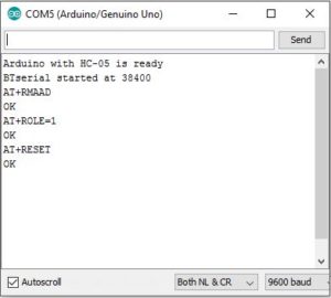
AT+RMAAD clears any previously paired devices.
AT+ROLE=1 puts the HC-05 in Master Mode
AT+RESET reset the HC-05. This is sometimes needed after changing roles.
Now enter the following
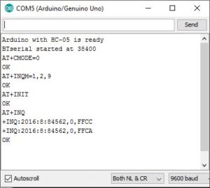
AT+CMODE=0
AT+INQM=0,5,9
AT+INIT
AT+INQ
AT+INQM=1,5,9, AT+INIT and AT+INQ require pin 34 to be HIGH.
If pin 34 is not HIGH then you will not receive any reply from these commands.
No message, no error message.
picture
AT+CMODE=0 allows the HC-05 to connect to any device
AT+INQM=1,2,9 set inquiry to search for up to 2 devices for 9 seconds
AT+INIT initiates the SPP profile. If SPP is already active you will get
an error(17) which you can ignore.
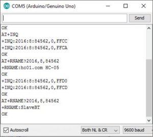
AT+INQ searches for other Bluetooth devices.
In the above screen shot you can see that the Master HC-05 found 2 Bluetooth devices.
+INQ:2016:8:84562,0,FFCC
+INQ:2016:8:84562,0,FFCA
One of these is the Slave HC-05. To find out we can use the AT+RNAME? command.
AT+INQ returns 3 values, the first is the address and this is the value we need. The second value is the class of the device and the third value is the signal strength (RSSI).
AT+INQ will only work if the HC-05 is in AT-Master Mode and after a AT+INIT command.
To get the name of the found devices we use the AT+RNAME command. The address is the first field returned by AT is +INQ:2016:8:84562,
When we enter the address we need to replace the colons with commas. The format is AT+RNAME?2016,8,84562 and AT+RNAME?2016,8,84562 Of course, you would use the address of your HC-05 Slave.
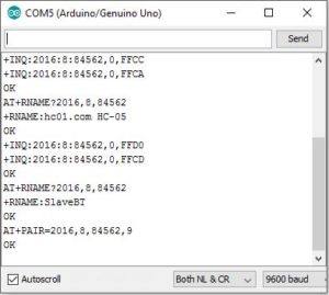
4. Pair the HC-05 with the HC-06
To pair we use the AT+PAIR=<addr>,<timeout> command. Enter “AT+PAIR=2016,8,84562,9″ (no quotes) If the Master HC-05 cannot pair with theSlave HC-05 within 9 seconds you will get an error message. If the pairing is successful you will get an “OK”
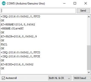
5. Bind the HC-06 to the HC-05
Bind using “AT+BIND=2016,8,84562″
6. Set the HC-05 to only connect with paired devices
We do this with the CMODE command – “AT+CMODE=1?
7. Link to the HC-06
Use the link command AT+LINK=<addr>
In my case “AT+LINK=2016,8,84562″. If all is well you will get the “OK” reply.
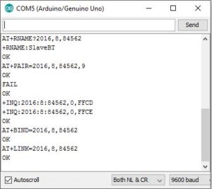
The LED on the Master HC-05 should have 2 quick blinks every 2 seconds (or so). The LED on the Slave HC-06 should be also blinking following the pattern of it’s master.You have now connected the Master HC-05 and the Slave HC-05
Now that the connection has been formed, the Master HC-05 will automatically connect to the Slave HC-05 every time they are turned on.Once the connection is formed the Master HC-05 will switch to communication mode. If you want to continue with AT Mode then you will need to reset the module with pin 34 HIGH or with the button switch closed.
Test The Connection
On the Master HC-05, remove the connection to pin 34 and upload the following sketch(no.4) to the Arduino connected to it. The sketch opens the BTserial at 38400 for communication mode.
Reset both Arduinos and remove power from the Master HC-05 and the Slave HC-05. Power on the Slave HC-05. The LED should be rapidly blinking 5 times per second. This indicates it is waiting for a connection or to be paired. Power on the Master HC-05. The LED will blink a couple of times when first on and then change to a the regular pattern of blinking quickly every couple of seconds.The LED on the Slave HC-06 will folow the pattern as of the Master HC-05. The modules are now connected.
Open the serial monitors and what ever you enter in one will appear the the other and visa versa
Every time the modules are powered on they should connect. If you find they do not connect then cycle the power to the Arduinos. Sometimes the Master HC-05 will get stuck trying to make a connection. In this case the LED on the Master HC-05 will either
1. quickly blink 3 times every couple of seconds.
This normally happens when the Slave HC-05 is turned off and then back on again without resetting the Master HC-05.The devices seem to connect more quickly when the Slave HC-06 is started first.
3. Arduino to Arduino by Bluetooth
if you did successfully link your Bluetooth module, this step is going to be easy. if not try to goup on the AT-MODE and find where you did a mistake. As on previous steps I explained how to connect a Master HC-05 to a Slave HC-05 so that when powered they automatically made a connection. Here we look at using that connection to get Arduinos talking over Bluetooth. Before continuing you need to have the Arduinos and BT modules set up as per the previous steps. Here I am using 2 HC-05s. One in master mode the other in slave mode.
Set Up
I am using 5V Arduino . We have designated one of the Arduinos as the master device. This is the one that initiates the connection and in the first example it is the one that sends the commands. Having a master and slave setup makes the programming a little easier.
To communicate with the BT modules I am using AltSoftSerial which uses pin 8 and pin 9. The AltSoftSerial library can be downloaded from and it will need to be added before you can compile the example and it will need to be added before you can compile the example sketches. Both BT modules are set with a communication baud rate of 9600. This can be changed but make sure you match the baud rate used when opening the software serial connection.
 //  open software serial connection to the Bluetooth module.
    BTserial.begin(9600);
Connecting the Bluetooth Modules
HC-05s have 3.3v TX and RX pins. 5V Arduinos will read 3.3v as HIGH so the BT modules TX pin can be connected directly to the Arduino RX pin. However, the Arduino TX pin needs to be converted to 3.3v before connecting to the BT modules RX pin. A simple way to do this is by using a voltage divider made from 2 resistors; I generally use 1 x 1K and 1 x 2K.
Arduino RX (pin 8) to BT module TX pin
Arduino TX (pin 9) to BT module RX pin via a voltage divider
Both Arduinos have the same connections to the BT modules.
Remote Control an LED
In the first example we get one Arduino to control an LED connected to a second Arduino. Communication is one way only and there is no error checking. Arduino #1 simply sends the commands LEDON and LEDOFF to the Arduino #2. When the Arduino #2 gets the commands it sets the LED accordingly.
Circuit
Arduino #1, the master device, just has the Bluetooth module. Arduino #2, the slave device we have the Bluetooth module and an LED (with a suitable resistor) on pin D3.

Sketches
The Sketch(no.5) on Arduino #1, the master device connected to the HC-05, simply sends the command LEDON, waits a second, sends the commands LEDOFF waits another second and then repeats indefinitely.
You will notice that the commands are contained within start and end markers, < and >.
BTserial.println("<LEDON>");
BTserial.println("<LEDOFF>");
Using start and end markers allows the receiving device to check that it has a full command before acting upon it.
The Sketch(no.6) on Arduino #2, the slave device, checks for data and if there is a start marker it starts to put the recieved data in to the variable receivedChars[ ]. When an end marker is received it sets the newData flag to TRUE. Any data not within the start and end markers is ignored.
When newData is TRUE we know we have a command to process. In this case we set pin D3 HIGH or LOW to turn the LED on or off.
That’s it hope you learnt something.
Ressources:
File:
Arduino Code:
Libraries:
Package includes:
1×HC05 Bluetooth Module