Description
This is a single channel relay shield, you can now turn on and off lamps, fans, solenoids, and other small appliances that run on up to 250VAC or DC power.
- The 8550 transistor drive, driveability.
- A fixed bolt holes for easy installation.
- It has a relay status indicator led Power LED(Green), 1 relay status indicator LED(Red)
- Relay control interface by single-chip IO.
- Low-level suction close, high-level release.
- Easy to use, simple 3 line structure.
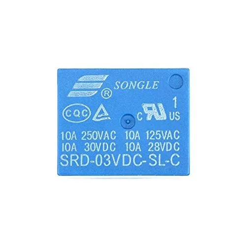
Getting started with the Single Channel 5V Relay Module (SONGLE)
Sometimes you want your Arduino to control AC powered devices like lamps, fans or other household devices. But because the Arduino operates at 5 volts, it cannot directly control these higher voltage devices. That’s where the relay module comes in. You can use a relay module to control the AC mains and Arduino to control the relay.
This tutorial walks you through how to setup the one channel relay module to switch on a lamp or other device, but let’s begin with a short introduction into relays.
How Do Relays Work?
A relay is an electromagnetic switch operated by a relatively small current that can control much larger current. Here’s a simple animation illustrating how the relay uses one circuit to switch on another circuit.
Initially the first circuit is switched off and no current flows through it until something (either a sensor or switch closing) turns it on. The second circuit is also switched off.
When a small current flows through the first circuit, it activates the electromagnet, which generates a magnetic field all around it.
The energized electromagnet attracts a contact in the second circuit toward it, closing the switch and allowing a much bigger current to flow through the second circuit.
When the current stops flowing, the contact goes back up to its original position, switching the second circuit off again.
Relay Basics
Typically the relay has 5 pins, three of them are high voltage terminals (NC, COM, and NO) that connect to the device you want to control.
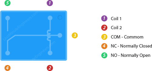
The mains electricity enters the relay at the common (COM) terminal. While use of NC & NO terminals depends upon whether you want to turn the device ON or OFF. Between the remaining two pins (coil1 and coil2), there is a coil that acts like an electromagnet.
When current flows through the coil, the electromagnet becomes charged and moves the internal contacts of the switch. At that time the normally open (NO) terminal connects to the common (COM), and the normally closed (NC) terminal becomes disconnected.
When current stops flowing through the coil, the internal contact returns to its initial state i.e. the normally closed (NC) terminal connects to the common (COM), and the normally open (NO) terminal reopens.
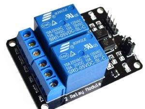
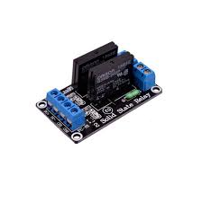
One Channel Relay Module
For this tutorial, we are going to use one channel relay module. However there are other modules with two, four and eight channels. You can choose the one that best suits your needs.
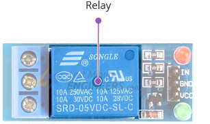
This module is designed for switching only a single high powered device from your Arduino. It has a relay rated up to 10A per channel at 250VAC or 30VDC.
Hardware required
The following illustration shows the wiring.

Arduino Code
Now that our hardware is all set up, let’s take a look at the code that turns the lamp on.
int RelayPin = 6;

void setup() {
	// Set RelayPin as an output pin
	pinMode(RelayPin, OUTPUT);
}

void loop() {
	// Let's turn on the relay...
	digitalWrite(RelayPin, LOW);
	delay(3000);

	// Let's turn off the relay...
	digitalWrite(RelayPin, HIGH);
	delay(3000);
}
Testing the circuit
It will turn on the lamp for 3 seconds and keep it off for the next 3 seconds.