Description
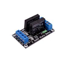
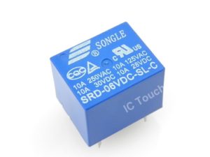
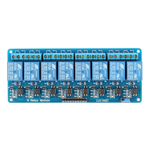
The four-channel relay module contains four 5V relays and the associated switching and isolating components, which makes interfacing with a microcontroller or sensor easy with minimum components and connections. The contacts on each relay are specified for 250VAC and 30VDC and 10A in each case, as marked on the body of the relays.
One of the most useful things you can do with an Arduino is control higher voltage (120-240V) devices like fans, lights, heaters, and other household appliances. Since the Arduino operates at 5V it can’t control these higher voltage devices directly, but you can use a 5V relay to switch the 120-240V current and use the Arduino to control the relay.
Four-Channel Relay Module Pinout
|
Pin Number |
Pin Name |
Description |
|
1 |
GND |
Ground reference for the module |
|
2 |
IN1 |
Input to activate relay 1 |
|
3 |
IN2 |
Input to activate relay 2 |
|
4 |
IN3 |
Input to activate relay 3 |
|
5 |
IN4 |
Input to activate relay 4 |
|
6 |
VCC |
Power supply for the relay module |
|
7 |
VCC |
Power supply selection jumper |
|
8 |
JD-VCC |
Alternate power pin for the relay module |
SPECIFICATION
- Supply voltage – 3.75V to 6V
- Trigger current – 5mA
- Current when the relay is active – ~70mA (single), ~300mA (all four)
- Relay maximum contact voltage – 250VAC, 30VDC
- Relay maximum current – 10A
How the 5V 4-channel relay works
The 4 channel relay module has three high voltage terminals (NC, C, and NO) which connect to the device you want to control. The other side has three low voltage pins (Ground, Vcc, and Signal) which connect to the Arduino.
- NC: Normally closed 120-240V terminal
- NO: Normally open 120-240V terminal
- C: Common terminal
- Ground: Connects to the ground pin on the Arduino 5V
- Vcc: Connects the Arduino’s 5V pin
- Signal: Carries the trigger signal from the Arduino that activates the relay
Inside the relay is a 120-240V switch that’s connected to an electromagnet. When the relay receives a HIGH signal at the signal pin, the electromagnet becomes charged and moves the contacts of the switch open or closed.
Normally open VS. Normally closed
The 4 channel relay module has two different types of electrical contacts inside – normally open (NO) and normally closed (NC). The one you use will depend on whether you want the 5V signal to turn the switch on or turn the switch off.
The 120-240V supply current enters the relay at the common (C) terminal in both configurations. To use the normally open contacts, use the NO terminal. To use the normally closed contacts, use the NC terminal.
Normally open
In the normally open configuration, when the relay receives a HIGH signal the 120-240V switch closes and allows current to flow from the C terminal to the NO terminal. A LOW signal deactivates the relay and stops the current. So if you want the HIGH signal to turn ON the relay, use the normally open terminal:
Normally closed
In the normally closed configuration, a HIGH signal opens the switch and interrupts the 120-240V current. A LOW signal closes the switch and allows current to flow from the C terminal to the NC terminal. Therefore, if you want the HIGH signal to turn OFF the 120-240V current, use the normally closed terminal:
Getting started with the 4 Channel 5V Relay Module
When the input terminals (IN1, IN2, IN3, IN4) are supplied with low level signals, you can see relay K1, K2, K3, K4 closed successively and repeat this cycle. In order to show its the ability of driving load more intuitively, 4 LEDs are connected to relay K1,K2,K3 and K4.
Hardware required
- Arduino UNO
- Breadboard
- 4 Channel Relay Module
- Jumper wires
Connecting the Hardware


Code for controlling 4 channel relay module
int ch=4; // number of relays
int relay[]={2,3,4,5}; // pin number of relays
int wait=2000;int i=0;
void setup() {
for(int i=0; i<ch; i++){
pinMode(relay[i],OUTPUT); // set relay pins as output
digitalWrite(relay[i],HIGH); // turn relay off
}
}
void loop() {
for(int i=0; i<ch; i++){
digitalWrite(relay[i],LOW); // turn relay ON
delay(wait);
}
for(int i=0; i<ch; i++){
digitalWrite(relay[i],HIGH); // turn relay OFF
delay(wait);
}
}
RESULTS
After to upload the code. You should see the relays open/closed one by one and the LEDs connected to K1,K2,K3 and K4 light up or go out with the relays opened or closed.